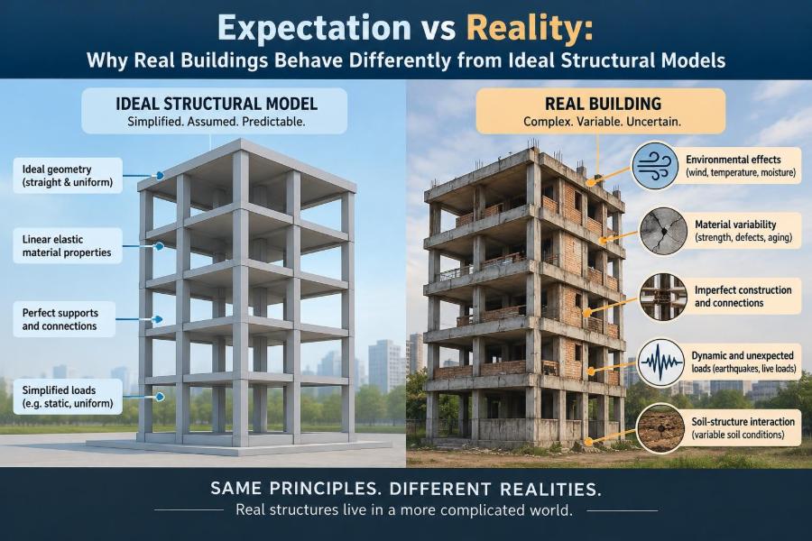

A beam calculation closes neatly. The bending-moment diagram is familiar, the load path is clear, and the deflection falls within the chosen limit. Then the completed building is loaded, heated by the sun, occupied, altered by trades, and exposed to weather.
It still follows the laws used in design—but not in the clean, isolated way shown in a classroom model. Floors participate when they were treated as separate. Connections rotate when they were assumed pinned. A wall stiffens a frame until a crack, opening, or movement joint changes the picture.
This gap is not evidence that structural analysis is useless. It is the reason structural engineering requires judgement alongside calculation. Models are deliberate simplifications, and their value depends on whether their assumptions fit the decisions being made.
For students, that is the transition from solving a structural problem to understanding a structure. For working engineers, it is a reminder that design is an ongoing process of choosing assumptions, checking sensitivity, detailing for uncertainty, and learning from what buildings actually do.
🧭 The model is a question, not the building
A structural model is a controlled representation of reality. It converts a three-dimensional, variable, imperfect physical system into elements, supports, material properties, loads, and boundary conditions that analysis software or hand methods can handle.
Every model leaves something out. The relevant question is not whether it is “perfect,” but whether it answers the engineering question safely and usefully. A simple beam model may be excellent for preliminary gravity design and unsuitable for assessing a transfer floor, vibration, or progressive-collapse behaviour.
Good modelling means making simplifications visible. When an assumption is stated, it can be checked, challenged, or replaced as the design develops.
📐 Idealization makes analysis possible
Engineers idealize members as lines, slabs as plates or diaphragms, supports as points or restraints, and loads as orderly patterns. These abstractions make equilibrium and compatibility tractable.
For example, treating a uniformly loaded beam as prismatic assumes its cross-section and stiffness are effectively constant along the span. That may be reasonable for a standard steel member, but less so for a tapered concrete beam, a haunched frame, or a member with major service penetrations.
Idealization is not a shortcut around physics. It is a way of retaining the physics that dominates a particular response while omitting secondary effects—provided they truly are secondary.
🧱 Materials are variable, not single numbers
Design models commonly use a specified strength and an elastic modulus. Actual concrete, steel, timber, masonry, and composite materials vary with manufacturing, curing, moisture, temperature, loading history, and location within a structure.
Concrete is especially instructive. Its stiffness evolves as it cures, decreases after cracking in tension, and changes over time through creep and shrinkage. A value used for one limit-state calculation cannot describe every stage of its life.
Design standards address variability through characteristic properties, safety factors, and prescribed rules. These measures manage uncertainty; they do not make the real material uniform.
🔩 Connections rarely behave as perfectly pinned or fixed
Textbook supports are often pinned, fixed, or roller supports. Real connections fall along a spectrum of rotational stiffness, strength, slip, and ductility.
A nominally simple steel connection may develop some moment resistance through end plates, bolts, angles, weld geometry, and connected-member restraint. A reinforced-concrete beam-column joint may be much closer to continuity than a simplified gravity model suggests.
This matters because connection stiffness redistributes moments and changes deflections, buckling lengths, and vibration characteristics. Assuming a joint is fully fixed when it is not can be unconservative; assuming it is fully pinned can sometimes conceal useful restraint but produce conservative member moments.
🧷 Boundary conditions are often the largest uncertainty
What holds a structure in place is frequently more influential than the member itself. Foundation flexibility, soil movement, adjacent construction, bearing details, and diaphragm action all affect the actual restraints.
Consider a column base idealized as fixed. It may rotate because of base-plate flexibility, anchor-rod elongation, grout deformation, or foundation rotation. Conversely, a base assumed pinned can gain restraint from a stiff pedestal and surrounding frame.
When results are sensitive to support conditions, engineers should test credible alternatives rather than rely on one convenient boundary condition.
🌍 Soil does not behave like a rigid support
Buildings transfer load to soil or rock, whose stiffness is spatially variable and depends on stress level, drainage, layering, and construction sequence. Settlement is therefore a structural issue as well as a geotechnical one.
Uniform settlement may cause little distress in a flexible frame. Differential settlement—one area moving more than another—can introduce unintended forces, crack finishes and masonry, distort services, and change load sharing.
A foundation model may use springs to represent soil support. Those springs are useful approximations, but their stiffness should be selected with geotechnical input and interpreted with awareness of their limits.
🏗️ Construction sequence changes the final force pattern
Analysis often begins with the finished structure, yet buildings are made in stages. Loads are introduced while some elements are incomplete, temporary supports carry force, and stiffness changes as concrete gains strength or connections are completed.
In a multistorey concrete frame, freshly cast slabs can transfer construction loads through shores and reshoring to lower levels. The force distribution during construction may differ substantially from the final gravity-load model.
Sequence also matters in steel erection, staged bridge construction, excavation support, and renovation. The “final state” alone may not identify the governing temporary condition.
⏳ Time-dependent effects are structural actions
Some movements occur slowly enough to be overlooked in a snapshot model. Concrete creep is gradual strain under sustained stress; shrinkage is volume reduction associated with moisture and hydration effects. Timber moisture movement and steel relaxation in certain systems can also matter.
Restrained movement generates force. A long concrete slab tied to stiff cores or walls may develop cracking or restraint stresses as it shrinks, even if its gravity-load analysis appears unremarkable.
Time-dependent analysis need not be elaborate for every project. It does need to be considered where span, restraint, material, finish sensitivity, or staged construction makes movement consequential.
🌡️ Temperature creates movement before it creates stress
Materials expand when heated and contract when cooled. If a building can move freely, temperature primarily produces displacement. If movement is restrained, it produces stress and can activate unexpected load paths.
Solar heating can create temperature gradients across a roof or façade. Seasonal changes can move long structures relative to cores, stairs, cladding, pipes, and neighboring blocks.
Expansion joints, sliding bearings, flexible connections, and properly located movement joints are not cosmetic details. They are mechanisms that allow the assumed movement to occur safely.
🪨 Cracking changes stiffness and load distribution
Many reinforced-concrete elements are designed with the expectation that tension-zone cracking will occur under service loads. Once cracked, their effective flexural stiffness is lower than the uncracked section stiffness.
That affects deflection, vibration, and how force flows through continuous systems. A stiff wall or slab region can become less influential after cracking, while alternative paths attract more load.
Cracking is not automatically a failure. Its significance depends on width, location, cause, exposure, water-tightness requirements, reinforcement detailing, and whether it indicates an evolving movement problem.
📉 Nonlinearity begins earlier than many models imply
A linear elastic model assumes stiffness remains constant and response scales directly with load. Double the load, and deflection and internal force double. Real structures depart from that ideal through cracking, yielding, contact, large displacement, gap closure, and changing support conditions.
Geometric nonlinearity becomes important when deflection changes the geometry enough to alter internal forces. The classic example is the P-Δ effect: axial load acting through lateral displacement creates additional moment.
Nonlinear analysis can represent these effects more realistically, but it introduces modelling choices and interpretation challenges. A more sophisticated analysis is only better when its inputs, validation, and purpose justify it.
🌀 Imperfections trigger instability
A perfectly straight, perfectly centered column under perfectly axial load is a useful concept, but no erected member is perfect. Initial crookedness, residual stress, load eccentricity, connection tolerances, and frame sway all influence buckling behaviour.
Design rules account for these realities through imperfection factors, effective lengths, notional loads, second-order checks, and member interaction equations. These are practical ways to include effects that may not be explicitly drawn in a model.
The key lesson is that stability is highly sensitive to stiffness and geometry. Small deviations can matter most in slender members and lightly braced systems.
🧩 Load paths are shared, not always assigned
Drawings may assign gravity load to beams, beams to girders, and girders to columns. In the completed structure, slabs, partitions, façades, stairs, walls, and connections may provide alternate paths or unintended restraint.
A concrete slab supported on a steel frame may act compositely if shear transfer is present, even where full composite action was not intended. A masonry infill wall can stiffen a frame under lateral loading, then crack and lose much of that contribution.
Unintended participation can reduce a local demand, but relying on it without deliberate detailing is risky. It may be absent in another bay, altered by renovation, or behave poorly under cyclic loading.
🧱 Diaphragms distribute lateral forces imperfectly
Floors and roofs are commonly treated as rigid diaphragms, meaning they distribute lateral load to walls and frames without significant in-plane deformation. This is often appropriate for compact reinforced-concrete slabs.
It can be less reliable for long narrow buildings, timber floors, metal deck diaphragms, floors with large openings, or layouts with discontinuous collectors. A flexible diaphragm can change which lateral elements receive force and how much they drift together.
Diaphragm modelling should reflect actual deck, slab, reinforcement, fasteners, openings, and load-transfer details—not simply the floor outline in plan.
🌬️ Wind is dynamic, directional, and local
Code wind procedures convert complex atmospheric behaviour into design pressures and combinations. They provide a rational basis for design, but real wind arrives in gusts, changes direction, and interacts with surrounding terrain and buildings.
Cladding corners, roof edges, canopies, parapets, and irregular forms can experience local effects that a global frame model does not reveal. Serviceability may be governed by acceleration, sway, façade movement, or occupant perception rather than member strength.
For unusual geometry or vibration-sensitive structures, specialist assessment may be needed. The appropriate level of refinement depends on the building and its exposure.
🌎 Earthquake response depends on the whole system
Seismic design is not simply a larger lateral-force calculation. Earthquake response depends on mass distribution, period, ductility, stiffness, damping, torsion, diaphragm behaviour, foundation interaction, and the sequence in which components yield or degrade.
A symmetric plan can still respond irregularly if stiffness is concentrated on one side, if a ground storey is unusually open, or if a transfer level interrupts the vertical load path. Nonstructural components may also affect movement or suffer damage at drifts that the primary frame can tolerate.
Seismic provisions use idealized spectra and response-modification concepts to create workable design procedures. Their intended ductile mechanisms must be supported by compatible detailing, not assumed from analysis alone.
👣 Serviceability is what occupants often notice first
Strength checks ask whether collapse or unacceptable failure is prevented at severe design actions. Serviceability checks address everyday performance: deflection, cracking, vibration, drift, ponding, door operation, façade movement, and finish damage.
A floor can be structurally safe yet feel lively under walking. A long-span beam can meet strength requirements yet deflect enough to crack brittle partitions or misalign glazing.
Serviceability predictions are uncertain because stiffness, damping, occupancy, and fit-out vary. Sensible limits, realistic effective stiffness, and early coordination generally produce better outcomes than trying to correct discomfort after completion.
🔧 Details decide whether assumptions survive construction
The most elegant global model cannot compensate for a detail that cannot transfer the force it assumes. Collectors, anchorage, lap splices, weld access, bearing lengths, edge distances, reinforcement congestion, and tolerances are all part of structural behaviour.
For instance, a drag strut in a diaphragm model only exists physically if its reinforcement or steelwork can develop the required force and connect it into the resisting element. A nominal line on a plan is not a load path.
Analysis establishes demand; detailing makes resistance real. Constructability review is therefore a structural check, not merely a drafting exercise.
📏 Tolerances introduce eccentricity and fit-up forces
Construction tolerances are necessary because members cannot be placed with mathematical exactness. Small offsets can create eccentric loading, reduce bearing, affect façade alignment, or require site adjustments.
Most well-detailed structures accommodate ordinary variation. Problems arise when a design has no tolerance path: a connection has no adjustment, reinforcement leaves no room for placement, or adjacent systems require incompatible movements.
Designers should distinguish between dimensions that are critical to force transfer and those that can tolerate variation. Clear tolerances and practical connection details reduce pressure for improvised field solutions.
🧑🔧 Changes on site can alter the structural system
Field modifications are sometimes necessary, but cutting an opening, moving a hanger, changing a connection, substituting a member, or drilling through a beam can affect capacity and stiffness beyond the immediate location.
A common misconception is that a small opening is harmless because it removes little material. Its position may interrupt reinforcement, reduce web shear capacity, concentrate stress, or compromise fire protection and durability.
Prompt communication matters. The safest response is not guesswork in the field, but review by the responsible design team with enough information to understand the existing condition and proposed change.
🏢 Nonstructural elements can become structural participants
Partitions, façades, ceilings, mechanical equipment, raised floors, and stairs are often classified as nonstructural because they are not intended to be part of the primary frame. They can still add mass, restrain movement, or interact with drift.
Rigid infill panels can attract lateral load. Heavy rooftop equipment can affect dynamic response. A stair connected between floors can restrain vertical shortening or seismic drift if joints and connections do not accommodate movement.
Coordination should therefore ask two questions: what loads do these elements apply, and what movements do they resist?
🔍 Monitoring provides evidence, not automatic answers
Survey points, crack gauges, strain sensors, accelerometers, and vibration measurements can reveal how a structure is behaving. Monitoring is especially useful when construction sequence, excavation, long-span deflection, settlement, or unusual movement creates uncertainty.
Measurements need context. A crack width observed once is less informative than its trend, location, orientation, environmental conditions, and relation to known construction events. Instrument data can also be misleading if sensors are poorly located or interpreted without a baseline.
Used well, monitoring closes the loop between model and reality. It can confirm assumptions, trigger investigation, and improve future designs.
🧪 Model calibration is an engineering skill
Calibration means comparing predictions with observations and adjusting the representation only where there is a defensible physical reason. It is not changing inputs until software produces a preferred answer.
Suppose a measured floor frequency is lower than predicted. Possible explanations include lower effective stiffness, higher participating mass, connection flexibility, or interaction with finishes. Each possibility should be tested against drawings, construction records, and observed behaviour.
A calibrated model should remain transparent: record what changed, why it changed, and which uncertainties remain. That record is valuable for assessment, alteration, and future operation.
⚖️ Conservative assumptions can conflict
“Be conservative” is useful advice only when the direction of conservatism is clear. Making every assumption severe at once can produce unrealistic force paths, hide governing combinations, or lead to inefficient details that are difficult to build.
For example, maximizing stiffness may attract more seismic force to an element, while minimizing stiffness may increase drift and second-order effects. A conservative choice for one check is not necessarily conservative for another.
Better practice is to identify the response being checked, select credible bounds, and understand how the result changes across them. Sensitivity is often more informative than one supposedly safe model.
🧮 Software performs calculations, not judgement
Modern analysis software can assemble thousands of elements quickly, but it cannot determine whether the idealized mesh, releases, diaphragm constraints, load combinations, or support springs represent the intended structure.
Warning messages, unusual reactions, abrupt force changes, and implausible deflected shapes are invitations to investigate. A model can converge numerically while describing a physically impossible structure.
Useful checks include equilibrium of total loads and reactions, hand estimates for key members, comparison with simple alternative models, review of deformed shapes, and direct tracing of major load paths.
📝 A practical workflow for realistic modelling
A robust process moves from simple understanding toward appropriate detail. It also leaves room for revision as information improves.
- Define the structural system, intended load paths, and critical performance objectives.
- Build a simple model or hand calculation to establish expected force and deflection ranges.
- Choose boundary conditions, stiffnesses, and releases that match the physical details.
- Check construction stages, movement effects, stability, and serviceability where relevant.
- Review sensitivity to uncertain inputs such as soil stiffness, cracking, diaphragm action, or connection restraint.
- Translate results into buildable details, then verify that the details preserve the assumed load path.
- Use site observations and monitoring, when available, to challenge important assumptions.
This workflow does not demand maximum complexity. It demands that complexity be added where it changes a decision.
🚫 Common modelling mistakes and better questions
| Common mistake | Better engineering question |
|---|---|
| Applying loads without tracing their route | Which physical elements collect, transfer, and resist this action? |
| Using default rigid diaphragms everywhere | Can this floor actually transfer in-plane force with limited deformation? |
| Assuming fully fixed or pinned joints by habit | What rotational stiffness and strength does the detail provide? |
| Checking only the completed structure | What temporary stages or movements govern during construction? |
| Accepting software output at face value | Do reactions, deformed shapes, and force patterns make physical sense? |
| Treating observed cracks as a single diagnosis | What mechanism, trend, restraint, and exposure condition explain them? |
The better questions are often simple. Their value lies in asking them before drawings, construction, or occupancy make a change expensive.
🎓 What students should carry beyond the classroom
Ideal problems teach essential mechanics: equilibrium, compatibility, constitutive behaviour, and stability. Those principles remain the foundation of all structural engineering.
The next step is to attach each mathematical condition to a physical feature. Where is the support? What provides the restraint? What would make the connection rotate? When does the load arrive? What happens after cracking or movement?
Developing this habit turns equations into insight. It also makes software easier to use responsibly because the engineer has an expectation against which to judge the output.
🤝 Collaboration reveals assumptions early
Architects, geotechnical engineers, contractors, façade specialists, building-services designers, and owners each hold information that affects structural behaviour. A transfer beam may be altered by duct routing; a foundation assumption may change after site investigation; a façade detail may restrain slab-edge movement.
Early coordination does not eliminate uncertainty, but it exposes it when options remain open. It is particularly valuable at interfaces: structure-to-façade, core-to-floor, foundation-to-frame, and new construction-to-existing building.
Clear sketches and plain-language explanations help others understand why a movement joint, collector, temporary brace, or no-drill zone is necessary.
🛡️ Design for uncertainty, not for fantasy
Structural safety does not depend on predicting every crack, gust, or construction variation exactly. It depends on using reliable principles, appropriate design provisions, robust load paths, ductile detailing where needed, inspection, and professional review.
Robustness often comes from continuity, redundancy, clear alternate load paths, and details that avoid brittle or disproportionate consequences from local damage. These features should be deliberate, not accidental side effects of a model.
Where uncertainty remains significant, the responsible response may be further investigation, a more suitable analysis, conservative detailing, monitoring, or a change in the structural concept.
💡 The core lesson: models guide decisions, reality tests them
Real buildings behave differently from ideal structural models because they are material systems built in stages, connected through imperfect details, supported by variable ground, and exposed to movement and changing loads over time.
The answer is neither to distrust analysis nor to pursue complexity for its own sake. It is to match the model to the question, test the assumptions that matter, and ensure drawings and construction preserve the intended behaviour.
The strongest structural model is not the one with the most elements; it is the one whose assumptions are understood, checked, and connected to the building that will actually stand.
When engineers keep asking how force, stiffness, movement, time, and detailing interact, the gap between expectation and reality becomes a source of better judgement—not an unwelcome surprise. 🏗️📐🔍