
Most people cross a bridge, enter a station, or ride an elevator without noticing the quiet system of decisions holding everything in place. The visible architecture may catch the eye, but structural engineering is what directs weight toward the ground, controls movement, and gives a structure a safe margin when conditions become difficult.
That work is not limited to spectacular towers and record-breaking spans. It is present in the slab beneath a kitchen floor, the braces behind a warehouse wall, the expansion joint at a bridge approach, and the reinforcement hidden inside concrete.
Learning to see these features changes the way buildings and bridges look. What seems like a simple beam, column, or wall is usually part of a continuous load path, designed around materials that stretch, shorten, crack, creep, vibrate, and age in very different ways.
Here are ten remarkable structural engineering facts—and the practical principles behind them—that are hiding in plain sight.
🧭 Start with the load path
A structure is not safe merely because its members are strong individually. It needs a load path: a continuous route that transfers gravity, wind, seismic, vehicle, and occupancy loads through the structure and ultimately into the soil or rock.
For a person standing on an upper floor, the basic route may be floor slab to beam, beam to girder, girder to column or wall, foundation, and ground. In reality, connections and neighboring members share parts of that journey.
When engineers inspect a building, they often ask a simple but powerful question: where does this force go? Missing, discontinuous, or unexpectedly altered load paths are behind many serious structural problems.
🔍 Fact 1: Concrete is strong in compression, not tension
Concrete handles compression—being squeezed—very well. That is why columns, arches, foundations, and dam-like forms can be made effectively from concrete. But ordinary concrete is comparatively weak and brittle in tension, where a material is being pulled apart.
A floor beam bends under load. Its upper region commonly shortens while its lower region elongates. Without help, tensile cracking would develop on the stretched side at relatively low loads.
This is not necessarily evidence of immediate failure. Controlled cracking is expected in many reinforced-concrete members, but its width, location, and progression matter for durability, serviceability, and safety.
🧵 Steel bars quietly solve concrete’s tension problem
Fact 1 has a partner: reinforced concrete works because embedded steel bars, called reinforcement or rebar, carry much of the tension after the concrete cracks. Steel is strong and ductile in tension, meaning it can deform substantially before fracture under suitable conditions.
Concrete and steel also have broadly compatible thermal expansion behavior, helping them act together over normal temperature changes. The ribs on rebar improve bond, allowing force to transfer between concrete and steel over a development length.
Reinforcement must be placed where tension is expected. A beam with steel near the bottom is not interchangeable with the same beam turned upside down; the bending demand and steel location must match.
🪢 Fact 2: Prestressing puts concrete under useful compression
Prestressed concrete uses high-strength steel strands that are tensioned before or after the concrete gains strength. When that tension is transferred into the member, it introduces compression that counteracts tension from service loads.
Think of lifting a stack of books with a tight strap around it. The strap pre-compresses the stack, so an applied load must first overcome some compression before opening a gap. Prestressing similarly helps keep concrete members less cracked under normal use.
This makes long, shallow floor units and bridge girders practical. The technique demands careful detailing, anchorage design, quality control, and allowance for time-dependent losses; it is not simply “stronger concrete.”
🌉 Why bridge girders can look surprisingly slender
Prestressing is one reason some bridge decks appear thinner than an observer might expect. Another is structural depth used efficiently: girders place material farther from the neutral axis, where it resists bending more effectively.
For a given span and loading, a deeper member is generally stiffer than a shallow one. Designers balance this against clearance below the bridge, roadway profile, aesthetics, fabrication, transport, and cost.
A slender bridge is therefore not automatically under-designed. Its shape may reflect prestressing, composite action with the deck, a continuous-span arrangement, or a carefully chosen structural system.
🔺 Fact 3: Triangles make trusses stable
A four-sided frame made of pin-like joints can change shape into a parallelogram without changing member lengths. A triangle cannot do that unless one of its sides changes length. This geometric stability is the essential idea behind a truss.
Trusses arrange straight members so most carry axial force: either tension or compression. That can use material efficiently, especially for roofs, cranes, and bridge spans where a solid beam would be heavier.
The triangular pattern does not eliminate design challenges. Compression members can buckle, connection plates need sufficient strength, and the overall truss must be braced out of its plane.
📐 Tension and compression leave different clues
Tension tries to elongate a member; compression tries to shorten it. Structural drawings and analysis models track these force directions because the two demands produce different failure risks.
- Tension members may yield, fracture, or fail at holes and connections.
- Compression members may crush, but slender ones often buckle first.
- Bending members usually contain both tension and compression across their depth.
On a truss bridge, members may look similar while carrying opposite forces. Altering one member, drilling an opening, or removing lateral bracing can therefore have consequences that are not visually obvious.
🪄 Fact 4: Columns often fail by buckling before crushing
A short, stocky column under centered load may reach the compressive strength of its material. A long, slender column can instead bend sideways suddenly: buckling. It is a stability failure, not simply a material-strength failure.
The familiar example is a ruler pressed between two hands. Hold it vertically and it can resist a force; make the unsupported length larger and it bows out much more easily.
Engineers reduce buckling risk by increasing section stiffness, reducing unsupported length with bracing, selecting end restraints realistically, and accounting for initial crookedness and unavoidable load eccentricity.
📏 Slenderness changes what “strong enough” means
Slenderness compares a member’s effective unsupported length with its stiffness-related cross-sectional dimensions. It explains why a thin steel rod and a thick concrete pier should not be judged only by their material strengths.
Columns also receive bending from wind, imperfect alignment, frame action, and loads applied away from the center. As they deflect, the axial load acting through that deflection can create additional moment, often called a second-order effect.
Good structural design evaluates the whole system. A column’s capacity depends on its bracing, connections, neighboring frames, and the way loads are introduced—not just on its visible size.
🏹 Fact 5: Arches turn vertical loads into compression
An arch can carry gravity load mainly through compression along its curved path. Masonry and unreinforced concrete, which are much more comfortable in compression than tension, are especially well suited to this behavior.
But an arch pushes outward at its supports. This horizontal thrust must be resisted by abutments, tie rods, adjacent structural elements, or a foundation system capable of carrying it.
Historic stone arches remain instructive because their stability depends as much on support conditions as on the stones above. Remove or weaken an abutment and the apparently robust arch can become unstable.
🧱 The line of thrust explains arch behavior
Engineers often visualize the resultant compressive force through an arch or masonry wall as a line of thrust. For masonry that cannot resist much tension, keeping this line within the thickness of the section is a useful stability concept.
Settlement, uneven loading, or changed supports can move the force path. Cracks may then form near locations where the masonry is being asked to resist tension.
This is why preserving old arches is not just about repointing joints or replacing visible stones. Investigation must include foundations, drainage, fill material, restraints, and any changes made nearby.
🌬️ Fact 6: Tall buildings are designed to move
No realistic tall building is perfectly rigid. Wind pushes laterally, causing the tower to sway and rotate slightly. The goal is not zero movement; it is movement within levels that protect structural performance, façades, services, elevators, and occupant comfort.
A stiff concrete core, perimeter moment frames, braced frames, outrigger systems, or combinations of these can resist lateral loads. The best choice depends on height, geometry, architecture, construction sequence, and local hazards.
Movement can be noticeable at upper levels during strong winds without indicating danger. However, unexpected movement, new cracking, or unusual sounds should always be assessed in context by qualified professionals.
🎵 Natural frequency makes motion feel different
Every structure has natural vibration modes, or patterns in which it prefers to move. A flexible tower may have adequate strength yet still require attention to serviceability: how it feels and performs during ordinary use.
Wind is not a steady hand pushing a building. Turbulence and vortex shedding can create changing forces. If the timing of external forcing aligns with a natural mode, the response can be amplified.
Engineers use wind-tunnel studies for some complex or unusually tall projects, along with analytical models and monitoring where appropriate. The objective is to understand realistic response, rather than assuming a simple uniform wind pressure tells the whole story.
⚙️ Fact 7: Tuned mass dampers counter building sway
A tuned mass damper is a large mass arranged to move relative to a structure, often with springs and damping devices. When tuned to a relevant vibration mode, its motion can reduce the amplitude of the building’s motion.
It works somewhat like a passenger shifting position to calm a wobbling platform—except the mass, stiffness, and damping are engineered precisely. Some systems use pendulum-like masses; others use liquid in tanks.
Dampers do not replace a proper lateral-force-resisting system. They supplement it, often improving comfort and reducing dynamic response under wind or certain vibration conditions.
🌡️ Fact 8: Bridges need room to expand and contract
Materials change length when temperature changes. A long bridge deck can experience meaningful movement over seasonal and daily temperature ranges, even when that motion is not visible to motorists.
Expansion joints and bearings accommodate controlled movement between bridge segments and at supports. Bearings may allow sliding or rotation while transmitting vertical loads to piers or abutments.
These components are exposed to water, dirt, de-icing chemicals, traffic impact, and repeated movement. Their maintenance matters because a seized joint or bearing can force unplanned stresses into girders, piers, and deck slabs.
🛞 A bridge deck is more than the driving surface
The pavement a driver sees is only the upper layer of a bridge deck system. Below it may be waterproofing, reinforced or prestressed concrete, steel girders, diaphragms, cross-frames, bearings, and substructure elements.
Water management is critical. Water carrying chlorides can reach reinforcement and promote corrosion; freeze-thaw action can worsen cracking and surface damage in susceptible conditions.
Drainage details rarely look dramatic, yet poorly directed runoff can shorten the life of deck components and foundations. Durable bridge design gives water a deliberate path away from vulnerable zones.
🌎 Fact 9: Foundations respond to the ground, not just the building
A foundation does not make a building “float” on soil. It spreads and transfers load into the ground while limiting settlement, sliding, overturning, and, where relevant, uplift.
The right foundation depends on soil and rock conditions, groundwater, nearby structures, load magnitude, and construction constraints. A shallow spread footing may be appropriate on competent material; a deep foundation may transfer load to deeper, stronger strata or use shaft resistance.
Two buildings with similar columns can need entirely different foundations because the sites are different. Geotechnical investigation is therefore a design input, not a late-stage paperwork exercise.
🪨 Settlement is often more troublesome when it is uneven
All ground deforms to some degree under load. Uniform settlement may be manageable if the entire structure moves gradually together. Differential settlement, where one part moves more than another, can distort frames, crack finishes, jam doors, and introduce unintended structural forces.
Causes can include variable soil layers, changing groundwater, inadequate compaction, leaking utilities, adjacent excavation, or uneven loading. The visible crack pattern alone seldom identifies the cause with certainty.
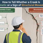
Investigation should distinguish cosmetic shrinkage cracks from movement-related distress. Monitoring, records, site observations, and subsurface information are usually more useful than a quick visual conclusion.
🌍 Fact 10: Earthquake design aims for ductility, not invincibility
During an earthquake, the ground moves and the structure’s mass resists that motion, creating inertial forces. Design seeks a clear, reliable load path for those forces and, in many systems, ductility: the ability to deform without sudden collapse.
Ductile detailing can encourage yielding in selected, accessible regions while protecting more brittle modes such as poorly confined concrete crushing, connection fracture, or column shear failure. This is why details can matter as much as member size.
Seismic design philosophy varies by location, building category, structural system, and governing requirements. It manages risk; it cannot promise that a severe event will produce no damage.
🧩 Capacity design chooses where yielding should occur
In a ductile frame, engineers prefer certain elements or zones to yield before others. A common conceptual objective is to avoid a weak story, in which one level becomes much less resistant than those above and below.
Connections, collectors, diaphragms, and foundations must be considered alongside beams and columns. A strong brace is of limited value if its connection tears away or if the floor cannot deliver lateral force to it.
This system-level thinking is one reason structural drawings contain dense reinforcement, weld, bolt, and connection information. The details are not decorative; they define how the intended mechanism can develop.
🔗 Connections are often the real structural story
Members are easy to notice. Connections are where forces change direction, combine, and transfer from one material or member to another. Bolts, welds, reinforcing bars, bearing plates, anchors, and joints are therefore central to structural performance.
A connection must address more than nominal strength. It may need to accommodate rotation, avoid brittle tearing, provide corrosion protection, allow erection tolerances, and remain inspectable.
Field changes deserve special care. Cutting a beam flange, relocating an anchor, enlarging a hole, or adding suspended equipment can alter the load path. Approval by the responsible design professional is the appropriate route, not an on-site guess.
🏢 Floors act like horizontal beams in the sky
Floor and roof systems commonly serve as diaphragms. Besides carrying people, furniture, and equipment downward, they collect wind or seismic forces and distribute them to walls, frames, or braces that resist lateral load.
A concrete slab can act as a relatively stiff diaphragm; a metal deck or timber floor may behave more flexibly depending on its construction. Openings for stairs, atriums, or services can interrupt force flow and require edge reinforcement or collectors.
That is why an apparently local renovation can affect global behavior. Removing walls or cutting large openings may change both gravity support and lateral-force distribution.
🧲 Composite action makes materials work together
Structural systems often gain efficiency when different components are connected so they resist load together. In a composite steel-and-concrete floor, shear connectors can make a steel beam and concrete slab act more like one deeper member.
The principle is simple: a beam bends more efficiently when its compression and tension zones are separated. The connection must prevent excessive slip between the materials so this combined action can develop.
Composite construction can reduce member sizes or material use, but it adds coordination requirements for studs, reinforcement, fire protection, sequencing, and construction loads before the concrete has hardened.
🕰️ Concrete keeps changing after it hardens
Concrete gains much of its early strength after placement, but its behavior continues to evolve. Creep is gradual deformation under sustained load, while shrinkage is volume reduction associated with moisture movement and other material processes.
In long spans, tall columns, and heavily loaded members, these effects can influence deflection, cracking, prestress losses, and force redistribution. They are accounted for through material models and detailing, not ignored because the concrete looks solid.
Construction timing matters too. A structure built floor by floor experiences changing loads and restraints, so engineers consider sequence when it materially affects behavior.
🛡️ Durability is part of structural safety
A member can be strong on opening day yet lose capacity over decades if moisture, chlorides, corrosion, chemical exposure, fatigue, or repeated freeze-thaw damage are not managed. Durability begins with selecting materials and details suited to the exposure.
Concrete cover protects reinforcement, coatings protect steel, drainage limits standing water, and access allows inspection and repair. These choices are often less visible than a dramatic structural form, but they strongly influence service life.
Maintenance is not an admission that a bridge or building was poorly designed. It is part of the lifecycle strategy for systems exposed to weather, traffic, use, and time.
🔄 Redundancy gives forces another route
Redundancy means a structure has more than one practical route for load transfer or more capacity pathways than a single critical element. If one component is damaged, the system may redistribute some load rather than failing immediately.
Redundancy is not identical to adding material everywhere. It can arise from continuous framing, multiple girders, ties, alternative supports, robust connections, and thoughtful detailing against progressive collapse.
There are limits: redistribution can create new overstresses, and some systems contain legitimate critical elements. Still, designing against disproportionate consequences is a valuable mindset when evaluating accidental damage and unusual events.
🧪 Models predict behavior; inspections test reality
Structural analysis models simplify the physical world. They estimate loads, stiffness, support conditions, and connections using assumptions that must be reasonable for the decision at hand.
Construction observation, material testing, surveys, and inspection provide a reality check. They can identify misplaced reinforcement, weld defects, unexpected ground conditions, or deviations from drawings before those issues become hidden or difficult to correct.
For existing structures, monitoring can help track crack movement, vibration, settlement, or corrosion indicators. Data is useful only when interpreted with an understanding of the structure’s design, condition, and environment.
🧰 Common visual clues—and why they need context
Cracks, stains, deflection, rust, and uneven surfaces can signal a concern, but none is a diagnosis by itself. A thin shrinkage crack in a nonstructural finish and a widening crack associated with support movement require very different responses.
| Visible condition | Possible explanation | Useful next step |
|---|---|---|
| Rust staining on concrete | Moisture reaching embedded steel or nearby metal | Assess extent, drainage, and concrete condition |
| New diagonal wall cracks | Movement, openings, or local stress concentration | Document location and check for progression |
| Persistent ponding on a deck | Poor drainage or surface deformation | Inspect drains, waterproofing, and slope |
Where there is a potential safety issue, such as significant deformation, loose concrete, impact damage, or rapidly changing cracks, access should be controlled and a qualified engineer consulted promptly.
🧠 What these hidden facts teach us
The ten facts connect to one core principle: structures work by directing forces through materials and geometry that suit them. Concrete uses compression, steel reinforcement supplies tension, trusses organize axial force, arches manage thrust, and foundations negotiate with the ground.
Movement is equally central. Buildings sway, bridges expand, concrete creeps, and soil settles. Good engineering does not pretend these effects disappear; it predicts, accommodates, controls, and inspects them.
The most reliable structures are not simply the heaviest. They have understandable load paths, appropriate connections, ductile or redundant behavior where needed, durable details, and a maintenance plan that respects real operating conditions.
Once you learn to look for load paths, movement joints, bracing, foundations, and connections, every building and bridge becomes a readable lesson in structural engineering. 🏗️ 🌉 🔍