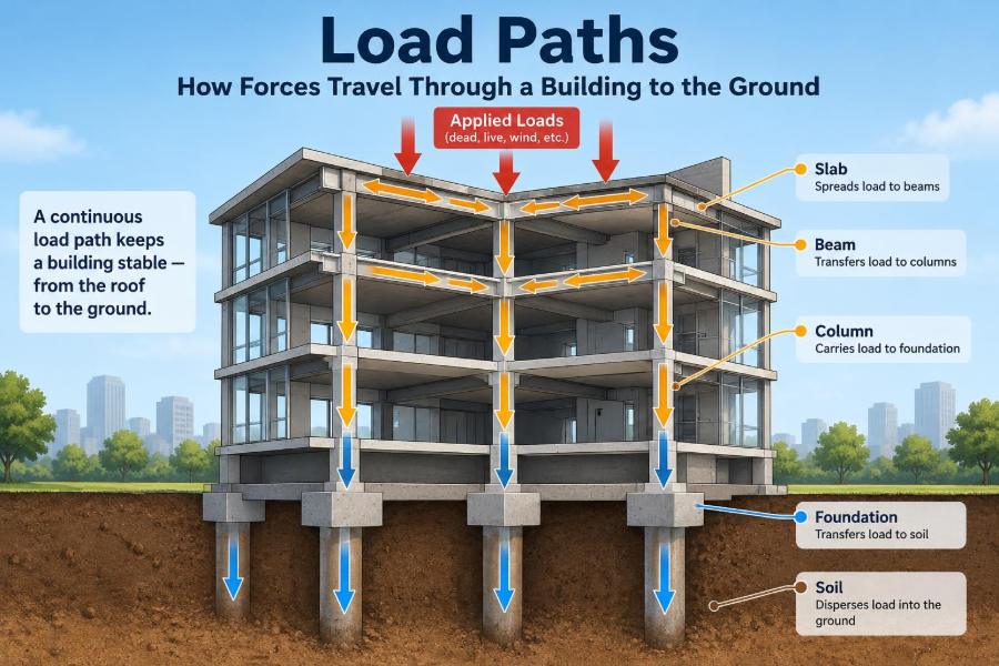

Picture a crowded office floor during a meeting. People, desks, filing cabinets, ceiling services, and the floor itself all add weight. Nobody standing in the room can see where that weight goes, yet the structure is continuously directing it downward and outward through a carefully connected system.
The same question appears on a smaller scale when someone removes a wall during a renovation. Is it just a partition, or is it carrying floor or roof load? The answer depends less on how substantial the wall looks than on the load path behind it.
Load paths are the hidden logic of buildings. They explain why a column needs a footing, why beam connections matter, why a missing brace can create instability, and why a seemingly minor opening can require major structural work.
Once you learn to trace forces from where they arise to the ground, drawings become easier to read and structural decisions become easier to question. The essential idea is simple; applying it to real buildings requires care.
🧭 What a Load Path Means
A load path is the route by which force travels through structural elements to a stable support, usually the ground. It is not a physical line drawn inside a building; it is a model of how connected members transfer actions from one to another.
For a typical gravity load, the route may be roof decking to joists, joists to beams, beams to columns or walls, columns to foundations, and foundations to soil. Each element receives force, resists it in an appropriate way, and passes it on.
A useful load path must be continuous, strong enough, stiff enough, and stable. If any link is absent, undersized, poorly connected, or supported by unsuitable ground, the intended route may not work as assumed.
⚖️ Loads Are Actions, Not Just Weight
In everyday language, a load sounds like weight. In structural engineering, it means an action applied to a structure. Some actions act vertically, while others push sideways, twist members, or create changing effects over time.
Engineers combine loads according to the governing design rules for the project. The resulting forces are then traced through the structure. A floor does not merely carry a number of kilograms; it carries a pattern of force whose location, duration, and direction matter.
- Gravity loads act mainly downward.
- Lateral loads, such as wind and earthquake effects, act mainly sideways.
- Environmental and imposed actions may include snow, rainwater ponding, temperature movement, machinery vibration, and earth pressure.
🧱 Dead Loads: The Building Carrying Itself
Dead load is the permanent weight of the building and its fixed components. Concrete slabs, steel framing, masonry walls, roofing layers, façade systems, and permanently installed equipment all contribute.
These loads are relatively predictable because they remain in place for most of the structure’s life. They can still change during a project: a heavier cladding choice, a thick topping slab, or additional services may increase the demand on members below.
Dead load accumulates as it moves down the building. A ground-floor column in a multi-storey building generally supports its own level plus the loads transferred from every supported floor above.
👥 Live Loads: People, Furniture, and Change
Live load, often called imposed load, comes from occupancy and movable items. People walking through a corridor, storage shelves in an archive, movable partitions, and equipment that can be relocated are common examples.
Unlike dead load, live load is variable. A classroom, warehouse, balcony, and residential room may all experience very different loading patterns because their use differs. Design requirements account for this uncertainty without assuming every possible item is present in the most severe arrangement at every moment.
Changes in use deserve special attention. Converting a lightly occupied office into storage can significantly change floor demand, even if no visible structural alteration is made.
🌬️ Lateral Loads Take a Different Route
Wind and seismic actions create horizontal forces and overturning effects. Their load paths are therefore different from the familiar vertical stack of slab, beam, column, and footing.
For wind, pressure on the façade and roof must transfer through cladding connections and supporting framing into a lateral-force-resisting system. That system may use shear walls, braced frames, moment frames, diaphragms, and foundations designed to resist sliding, uplift, and overturning.
Earthquake response is more complex because the ground moves and the building’s mass resists that motion through inertia. Still, the central question remains the same: where does each force go, and are all connections along the route capable of transferring it?
📐 Load Direction Changes at Every Transfer
Forces rarely travel straight downward without change. A horizontal floor slab carries distributed vertical load, delivers concentrated reactions to beams or walls, and may transfer in-plane lateral forces to a core wall or braced bay.
At each transfer, engineers consider both force and deformation. A beam can support a wall above, but if it deflects too much, finishes may crack, doors may bind, and the wall may be damaged even when collapse is not expected.
This is why structural design is not simply a search for the strongest member. Members must work together with compatible movement and clearly designed connections.
🏠 The Roof as a Starting Point
A roof is often the highest point in a gravity load path. Roof finishes, insulation, decking, snow where relevant, maintenance loads, and equipment are supported first by the roof’s immediate framing.
In a conventional timber roof, sheathing may bear on rafters, rafters may bear on exterior walls or ridge support, and those supports eventually lead to foundations. In a steel roof, metal deck commonly spans to joists or purlins, which frame into girders and columns.
Roof geometry matters. Sloped members can develop both vertical and horizontal reactions, so ties, ridge beams, or thrust-resisting walls may be essential. A roof that appears simple architecturally can have a demanding structural path.
🪜 Floors Spread Loads Across an Area
Floor systems collect loads across rooms rather than at a single point. A slab, deck, or sheathed timber floor acts as a surface that distributes load to its supporting members.
The direction in which a floor spans is fundamental. One-way systems mainly transfer load between two opposite supports, while two-way slabs distribute load in two directions, depending on geometry and support conditions.
Openings for stairs, elevators, ducts, and atriums interrupt the normal flow. The load that would have crossed the opening must be redirected around it with headers, trimmers, edge beams, or reinforced framing.
📏 Tributary Area Connects Surface Load to Members
A tributary area is the portion of a floor or roof whose load is assigned to a particular support. It is a practical way to convert an area load into a line load on a beam or a concentrated reaction on a column.
Imagine parallel joists spaced evenly across a floor. Each interior joist commonly receives load from half the spacing on one side and half on the other. A beam supporting those joists receives the reactions from all joists framing into it.
Tributary-area sketches are excellent early design and checking tools. They are simplifications, however; real distribution can be affected by stiffness, continuity, slab action, and connection behavior.
🪵 Joists and Secondary Beams Collect Local Load
Joists, purlins, and secondary beams are the close-spaced members that support decks, slabs, or sheathing directly. Their role is usually to collect distributed load over a relatively small width and deliver it to primary framing.
They often behave primarily in bending. The top and bottom of a bent member experience compression and tension in opposite directions, while shear is greatest near supports. Openings, notches, holes, and concentrated equipment loads can change this behavior substantially.
Secondary framing may look repetitive, but its alignment matters. A misplaced joist, unframed edge, or unsupported deck seam can interrupt both gravity support and diaphragm action.
🏗️ Primary Beams Gather Reactions
Primary beams, girders, and transfer girders receive reactions from several joists, secondary beams, or slabs. Their loads are less uniformly distributed than the floor surface load that began the sequence.
A beam may carry a uniform load over part of its length, point loads where other members frame into it, and torsion if those loads arrive away from its centerline. The support reactions then become concentrated loads on columns or walls.
When framing plans change, beam loading can change quickly. Moving a column line, adding a hanging wall, or shifting a stair opening should trigger a new review of the complete tributary path.
🧱 Bearing Walls Transfer Load by Compression
A bearing wall carries load mainly in compression down its height. Masonry, reinforced concrete, engineered wood, and light-frame walls can all serve as bearing walls, although their detailed behavior differs.
Openings create concentrated regions of force. A lintel, header, or reinforced beam above a door or window redirects wall load to side supports called jambs or piers. Those supports then need a route to adequate support below.
Load-bearing walls should align where possible from roof to foundation. Offsets are possible, but every offset introduces a transfer element that must be designed for the new force pattern and deformation demand.
🔩 Columns Concentrate Building Loads
Columns are vertical members that transfer concentrated reactions between levels. Because they gather load from beams, slabs, and upper columns, their forces can become large even when they appear slender.
An idealized column carries purely axial compression. Real columns may also experience bending because of frame action, accidental eccentricity, uneven loading, construction tolerance, or connections that do not align perfectly with the member centerline.
Column continuity is particularly valuable. Stacking columns directly over one another produces a simple, efficient route; shifting them may require transfer beams, deeper structure, and more demanding connection design.
🔄 Transfer Structures Solve Alignment Problems
Architecture does not always permit supports to stack neatly. A ground-floor lobby may need open space below a grid of apartment walls, or a parking level may use a different column layout from the floors above.
A transfer beam, transfer slab, truss, or deep wall redirects loads from one support arrangement to another. These systems are legitimate structural solutions, but they are not free shortcuts. They can be heavy, deep, costly, and sensitive to deflection and construction sequencing.
Where a transfer is unavoidable, engineers pay close attention to the force entering it, the reactions leaving it, and the supports below. A transfer element does not end the load path; it changes its route.
🧩 Connections Are Part of the Structure
Members cannot transfer force merely by touching. Bolts, welds, reinforcing bars, bearing plates, anchors, screws, straps, grout, and concrete confinement all help create the actual path between components.
A steel beam may be adequate in bending while its end connection lacks sufficient shear capacity. A timber post may be strong enough in compression while the connector beneath it is unable to transfer uplift or lateral load. In both cases, the system is limited by the connection.
Trace loads through connections, not just through member names. This habit prevents a common conceptual error: assuming the diagrammatic meeting of two members automatically creates a capable structural joint.
🧠 A Connection Needs the Right Type of Resistance
Connections transfer different actions in different ways. Some are intended to act as simple shear connections; others must resist moment, axial force, tension, compression, torsion, or combinations of these.
| Action arriving at a connection | What the connection must provide |
|---|---|
| Beam end reaction | Shear transfer and adequate bearing or fastener capacity |
| Braced-frame force | Axial tension and compression path into braces and supports |
| Moment-frame joint | Rotational restraint and transfer of tension-compression couple |
| Roof uplift | Continuous tension ties to resisting foundations or dead weight |
The table is a conceptual guide, not a connection design method. Actual details depend on material, geometry, load combinations, ductility requirements, and the applicable design standard.
🌐 Diaphragms Gather Sideways Forces
A diaphragm is a floor or roof assembly that acts in its own plane to collect and distribute lateral forces. Concrete slabs, steel deck with appropriate attachments, and wood structural panels can all serve this role when designed and detailed accordingly.
Think of a diaphragm as a horizontal plate connecting vertical lateral elements. Wind acting on a façade may enter the floor diaphragm, travel across it as in-plane shear, and arrive at a shear wall, braced frame, or core.
Large openings, irregular shapes, abrupt stiffness changes, and weak collectors can complicate diaphragm behavior. A floor may be strong for vertical occupancy loads yet inadequate as a lateral diaphragm if its in-plane connections are not addressed.
🛡️ Shear Walls, Braces, and Moment Frames
Buildings need a deliberate lateral system, not simply a collection of vertical members. Three common approaches are shear walls, braced frames, and moment-resisting frames.
Choosing a lateral route
- Shear walls resist in-plane shear and overturning through wall action. They are often efficient around stairs, elevators, and service cores.
- Braced frames use diagonals that work largely in axial tension and compression. They can be material-efficient but may affect façade openings and circulation.
- Moment frames resist lateral load through rigid beam-column joints. They can preserve open bays but require carefully designed, ductile connections.
Many buildings combine these systems. The choice depends on height, layout, material, seismic and wind demands, architectural constraints, foundation conditions, and construction method.
⬇️ Foundations Spread Force into Soil
Foundations receive structural reactions and spread them into the supporting ground. A column may bear on an isolated pad footing, a wall may sit on a strip footing, or the structure may use a mat foundation, piles, drilled shafts, or another system suited to the site.
Soil is part of the load path. Its strength, stiffness, groundwater conditions, layering, and potential for movement influence foundation behavior. The same footing geometry can perform differently on different sites.
Foundation design also considers uplift, sliding, overturning, settlement, and interaction among nearby footings. Sending force into the ground is not enough; the ground must accept it within acceptable performance limits.
🌍 Bearing Capacity Is Only Part of Ground Performance
It is tempting to think that soil design is only about whether the ground can support a calculated pressure. Settlement is equally important. A foundation may have sufficient bearing resistance but still move enough to damage finishes, utilities, cladding, or structural elements.
Differential settlement, where one part of a building settles more than another, is often more problematic than uniform movement. Stiff structures can redistribute some forces, but they may also develop cracking or unintended stresses when supports move unevenly.
Geotechnical investigation helps establish assumptions for the final segment of the path. Structural and geotechnical design must therefore be coordinated rather than treated as separate exercises.
↕️ Uplift Requires a Downward-Tension Path
Not all critical forces push down. Wind can create uplift on roofs and can overturn a whole building, placing one side of its foundation in tension. Seismic effects can also reverse force directions repeatedly.
An uplift path may run from roof sheathing to rafters, from rafters to wall plates, through hold-downs and walls, into anchors, and finally into a foundation with enough weight or anchorage to resist the pull.
Gravity-only thinking misses these routes. A connection adequate for a member bearing downward may not be adequate when that member is trying to lift away from its support.
🔁 Load Reversal Changes What Matters
Lateral actions can reverse direction. A brace that carries tension under wind from one direction may face compression when wind comes from the other. Connections, anchors, and collectors must be checked for the force patterns they can actually experience.
Load reversal is particularly relevant for elements that are slender in compression, such as some braces. It can also affect bolts, welds, reinforcing details, and the behavior of gaps or bearing surfaces that engage only in one direction.
Designers do not assume one convenient force direction is enough. They examine the governing cases required by the applicable code and the structural model.
📍 Discontinuities Create Force Concentrations
A discontinuity is a sudden change in the structural route: a missing wall below another wall, a large opening in a shear wall, a setback, a cantilever, or a dramatic change in stiffness between adjacent levels.
These locations tend to concentrate forces and deformation. For example, a continuous wall that stops at a podium level needs its load redirected through a transfer system; a lateral wall interrupted by an open storefront may create high demands in the remaining supports and collectors.
Discontinuities are not automatically unsafe. They simply require explicit analysis, clear detailing, and construction that matches the design intent.
🏢 Soft and Weak Levels Need Careful Lateral Design
A building level with substantially less stiffness or strength than the floors above can attract large drift and damage during lateral movement. Open parking or retail levels beneath more heavily partitioned upper floors are familiar configurations that can create this concern.
The issue is not that open space is prohibited. The structural system must be designed so the open level has a credible lateral path, sufficient strength, and suitable deformation capacity for the project’s hazards.
When reviewing a concept, ask where the lateral walls or frames continue through the open level. If they disappear, what replaces their function?
🧱 Openings Redirect Both Gravity and Lateral Forces
A door in a bearing wall and a penetration through a diaphragm are both interruptions in a force-carrying surface. The structure needs framing around the opening to bridge or redistribute the interrupted load.
For gravity systems, headers and edge members carry load around openings. For diaphragms and shear walls, boundary members, collectors, chords, and reinforced edges may be needed to carry in-plane actions around voids.
Field-created openings deserve particular caution. Cutting a hole for a new stair, mechanical duct, or service route can remove material that was essential to a load path, even when the opening looks modest.
🔍 A Simple Method for Tracing a Load Path
Students and practitioners can make load paths visible with a disciplined sketching process. Start with one specific load, rather than trying to understand the entire building at once.
- Identify the load source: a roof area, occupied floor zone, façade panel, or equipment item.
- Mark the first element that supports it and the direction that element spans.
- Follow reactions into the next larger members or supporting walls.
- Continue through connections, vertical supports, foundations, and soil.
- For lateral loading, trace through diaphragms, collectors, lateral elements, and foundation restraint.
- At every change, ask whether the receiving element and connection can resist the arriving action.
Use arrows, tributary boundaries, and separate colors for gravity and lateral paths. A clear hand sketch often reveals missing support lines before detailed calculations begin.
🧮 Calculations Verify the Sketch
A load-path sketch is not a substitute for analysis. It establishes the physical story that calculations, models, and drawings must support. If the analytical result cannot be explained as a credible path through real members and joints, it deserves investigation.
Hand calculations are valuable for estimating tributary loads, reactions, bending, and axial force. Computer models can handle complex geometry and system interaction, but their output depends on assumptions about supports, stiffness, releases, diaphragm behavior, and load application.
Good engineering uses both. Simple checks build intuition; detailed analysis tests the system at the required level of rigor.
💻 Model Boundaries Can Hide Missing Paths
Structural software may connect nodes perfectly even when a buildable connection has not been developed. It may also distribute forces through idealized rigid diaphragms or supports that do not reflect actual flexibility.
Common modeling questions include: Is the slab truly capable of acting as assumed? Does a beam frame into the column at the modeled location? Is the foundation restraint realistic? Has a wall opening been represented? Are members inadvertently connected through a shared node?
Models are powerful tools, not independent evidence. The engineer still needs to inspect the intended route visually and detail it in a form that can be constructed.
🚧 Construction Sequence Can Change the Path Temporarily
A completed building may have a clear final load path, while the partially built structure passes through different and sometimes more vulnerable stages. Wet concrete, temporarily unbraced steel, removed shoring, and incomplete diaphragms can all change how forces travel.
For example, a composite floor may not achieve its final behavior until concrete has cured and connections are complete. A precast panel may need temporary bracing before permanent ties are installed.
Construction-stage design and site coordination matter because a safe final configuration does not automatically guarantee safe erection. Temporary works require appropriate engineering and planning for the actual sequence.
🛠️ Renovations Often Interrupt Hidden Structure
Renovation work is a frequent source of load-path problems because the structural system may be concealed behind finishes. Removing a wall, coring a slab, adding rooftop equipment, or replacing cladding can alter loads and supports in ways that are not obvious from a floor plan.
Before changes are made, information may be gathered from original drawings, field measurements, exploratory openings, material investigation, and a qualified structural assessment. Existing buildings can differ from drawings because of prior alterations or construction variation.
Never treat a wall as nonstructural solely because it is thin, inconvenient, or not centered in a room. Its role must be established from evidence.
⚠️ Common Load-Path Mistakes
Most load-path errors come from overlooking a transition rather than misunderstanding basic gravity. The following mistakes are especially common in early concepts, reviews, and alterations.
- Following a beam to a column but not checking how the beam reaction enters the column.
- Stopping at the foundation without considering soil movement, uplift, or sliding.
- Assuming a floor slab is automatically a diaphragm without checking its connections and openings.
- Ignoring point loads created by posts, equipment, and walls that land between supports.
- Adding a heavy item at roof or floor level without tracing demand through every level below.
- Relying on architectural alignment when the structural supports do not actually align.
The practical cure is straightforward: trace every significant load all the way to a resisting support, then trace the equal-and-opposite reactions through the connections.
📋 Questions to Ask During a Drawing Review
Load-path review should happen early, when changes are still inexpensive. A few focused questions can expose issues that are difficult to resolve after architecture and services are fixed.
- What supports each slab, roof area, wall, and façade zone?
- Where do concentrated reactions occur, and what is directly below them?
- Which elements resist wind and seismic actions in each principal direction?
- How do diaphragms transfer force to those elements?
- Where are the transfers, offsets, openings, and changes in stiffness?
- How are uplift, sliding, and overturning carried into the foundation system?
These questions do not replace formal design checks. They create a structured conversation between structural, architectural, geotechnical, and construction teams.
🤝 Load Paths Depend on Coordination
Structural clarity can be lost when disciplines make isolated changes. A larger duct opening can cut a beam web; a revised façade can add eccentric load; a relocated stair can disrupt a diaphragm; a landscape change can affect foundation drainage or retaining pressures.
Coordination works best when the structural concept is communicated in plain language as well as drawings. Architects and contractors do not need to perform structural calculations, but they benefit from knowing which walls, beams, bracing lines, openings, and connections are critical.
Clear documentation also reduces site improvisation. When an unusual support or collector is identified early, it is more likely to be installed as intended.
🎯 Efficiency Comes From Directness, Not From Removing Members
An efficient structure usually has relatively direct, repeated, and well-aligned load paths. This does not mean every building should be a simple box, nor does it mean that fewer members always make a better design.
Long spans, cantilevers, open plans, setbacks, and expressive forms can be entirely appropriate. They simply require the structure to redirect forces through stronger, deeper, stiffer, or more carefully connected elements.
The best early question is often not “Can this member carry it?” but “What is the simplest credible route from this load to the ground?” A direct answer often improves cost, constructability, and reliability together.
🏁 The Core Principle: Continuity From Load to Ground
Every structure is a connected chain of force transfers. Gravity loads move through floors, beams, walls, columns, foundations, and soil. Lateral loads move through cladding, diaphragms, collectors, walls or frames, anchors, and foundations. Uplift and reversal demand paths in the opposite direction as well.
The elements may be timber, steel, concrete, masonry, or a combination. The governing principle does not change: forces need a continuous route through real members and real connections to supports that can resist them.
When evaluating any building detail, follow the force, identify each transfer, and look for interruptions. That simple habit is one of the most durable tools in structural engineering.
A safe structural concept is not defined by isolated strong components; it is defined by complete, connected load paths from every significant force to the ground. 🏗️📐🌍