
A floor that feels slightly bouncy, a shelf that visibly sags, or a bridge girder that settles under traffic all point to the same structural behavior: deflection. The member may be strong enough not to break, yet still move enough to create a practical problem.
That distinction matters. A beam can satisfy a strength check while causing cracked finishes, ponding on a roof, misaligned doors, uncomfortable vibration, or an impression that the structure is unsafe. Serviceability is often where users first experience structural performance.
For a simply supported beam, the underlying mechanics are approachable. With a clear loading diagram, a realistic stiffness value, and the right boundary conditions, an engineer can estimate deflection before detailed computer analysis is needed.
The goal is not to memorize a long list of formulas. It is to understand what makes a beam bend, choose a formula that matches the real situation, and judge whether the result is credible.
📐 What Deflection Actually Means
Deflection is the displacement of a point on a structural member from its original position under load. For a horizontal beam carrying gravity loads, the displacement is usually vertical and downward.
Engineers often use the symbol δ for a deflection value. The largest value, called the maximum deflection, is commonly the first quantity checked because it usually governs appearance, function, or a serviceability limit.
Deflection is not the same as stress. Stress describes internal force intensity; deflection describes movement. Both must be checked because a beam can be low-stress but flexible, or stiff but highly stressed.
🏠 Why a “Safe” Beam Can Still Be Unacceptable
Ultimate strength design asks whether the beam can resist factored actions without collapse or another limit-state failure. Deflection checks ask whether the beam performs acceptably under normal use.
A long steel beam may carry its design load with ample strength but sag enough to crack a brittle partition below it. A timber joist may be structurally adequate yet create noticeable floor vibration or a sloping finish.
Deflection therefore belongs to serviceability design. Applicable building codes, material standards, project specifications, and the sensitivity of supported elements determine the allowable movement. There is no universal limit that is appropriate for every beam.
🧱 The Simply Supported Beam Model
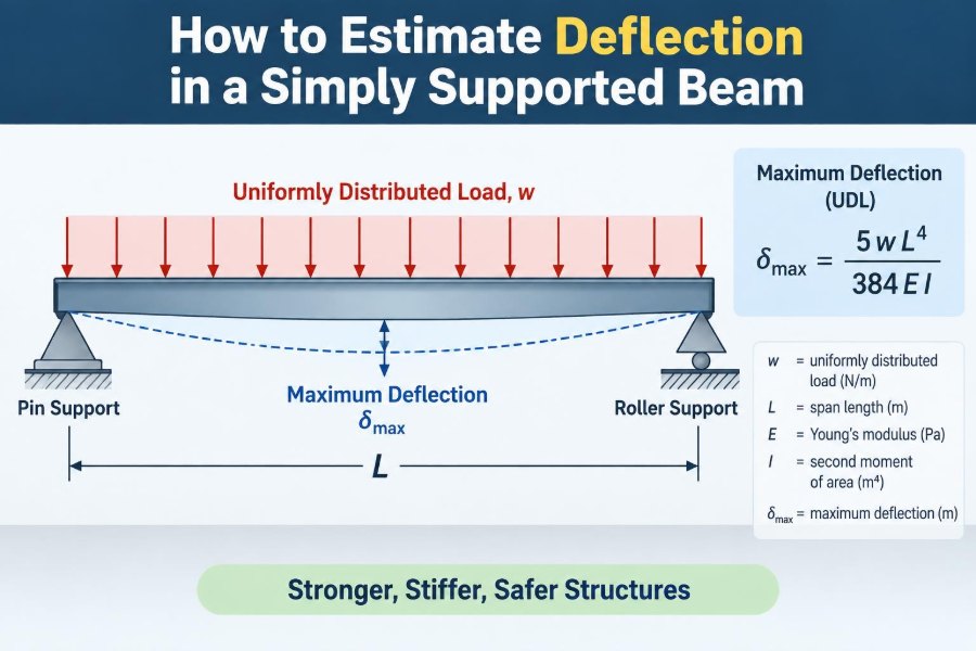
A simply supported beam has a support at each end that prevents vertical movement. In the idealized model, one support acts as a pin and the other as a roller, allowing the beam to rotate at both ends.
The pin prevents horizontal and vertical translation; the roller prevents vertical translation but permits horizontal movement. This arrangement avoids creating an unintended axial restraint when temperature changes occur.
Most importantly for deflection, the ends have zero vertical deflection but are free to rotate. This differs fundamentally from a fixed-end beam, whose end rotations are restrained and whose deflections are generally smaller under the same load.
🗺️ Start With a Correct Structural Idealization
Before using an equation, draw the beam, supports, span, and every load. Label the span L, point loads as P, and uniformly distributed loads as w.
Ask what the beam truly supports. Is a wall load spread along a bearing length? Is an equipment load applied at one location? Does a slab deliver a uniform line load, or does tributary width vary along the span?
A simple formula is only as good as its model. Replacing a localized heavy load with an average distributed load can substantially understate the local curvature and may understate maximum deflection.
⚖️ Separate Load Types Before Combining Them
Loads are commonly grouped as dead load, live load, roof live load, snow, equipment load, and other actions defined by the governing design basis. For a deflection calculation, the relevant issue is both magnitude and duration.
Dead load is sustained: self-weight, permanent finishes, fixed services, and permanently installed equipment. Live load may be intermittent. A storage beam, however, can experience sustained loading even when the nominal load category is live load.
Keep load cases separate until the governing criteria are known. Total-load deflection and live-load deflection may both require review, while long-term deflection in concrete or timber needs additional consideration.
📏 Convert Area Loads Into Beam Line Loads
Many gravity loads begin as an area load, such as kN/m² or psf. A beam formula needs a line load, such as kN/m or lb/ft. The conversion comes from tributary width.
For a uniform slab load q supported over a tributary width b, the line load is:
w = q × bFor example, a 4 kN/m² area load delivered over a 3 m tributary width becomes a 12 kN/m line load before adding the beam’s own self-weight. Use consistent units throughout; mixed millimetres, metres, and kilonewtons are a common source of large errors.
🔢 The Four Main Drivers of Beam Deflection
Elastic beam deflection is governed primarily by load, span, elastic modulus, and second moment of area. The relationship is captured by the product EI, called flexural rigidity.
- Load: More load creates more bending and more deflection.
- Span: A longer span is much more flexible than intuition often suggests.
- Elastic modulus, E: A stiffer material has a larger E value.
- Second moment of area, I: A deeper or better-shaped cross-section bends less.
For common elastic cases, deflection varies inversely with EI. Double EI, and the elastic deflection is halved, provided the assumptions remain valid.
📈 Why Span Has Such a Powerful Effect
For a simply supported beam with a full-span uniform load, maximum deflection is proportional to L4. For a central point load, it is proportional to L3.
That means a modest increase in span can demand a major increase in stiffness. If the span doubles under the same uniform load and section, the calculated elastic deflection becomes sixteen times larger.
This is why a section that works well over a short opening may perform poorly over a longer room. Increasing depth, adding an intermediate support, or changing the framing layout is often more effective than merely adding material to flanges.
🏗️ What Elastic Modulus E Tells You
The elastic modulus E measures how much a material strains under stress in its linear elastic range. A higher modulus means less strain for a given stress and, all else equal, less beam deflection.
Structural steel has a relatively high and predictable elastic modulus. Timber has a lower modulus that varies by species, grade, moisture condition, orientation, and product type. Concrete stiffness is more complicated because cracking, creep, shrinkage, and age affect behavior.
Use the modulus required by the applicable material standard or design method. Selecting a familiar generic value rather than the specified design property can make a calculation look precise while being unsuitable for design.
📦 Why Beam Depth Is So Effective
The second moment of area I describes how a section’s area is distributed about its neutral axis. Material farther from that axis contributes strongly to bending stiffness.
For a rectangular section of width b and depth h bending about its strong axis:
I = bh³ / 12Depth is cubed. Doubling the depth of a rectangular member, while keeping width constant, increases I by eight times. This is the structural logic behind deep joists, I-shapes, box girders, and trusses.
🔄 Strong-Axis and Weak-Axis Bending
A section can be very stiff about one axis and comparatively flexible about the other. A steel wide-flange beam placed upright normally bends about its strong axis; placed on its side, it may have far less useful stiffness.
Always verify the orientation used to obtain I. The correct section property must match the actual loading direction, not simply the largest value listed in a catalogue.
For unsymmetrical sections, bending may involve principal axes and lateral effects. Basic formulas are still useful for preliminary work, but the model may need refinement when the load does not pass through the appropriate shear center or when torsion is significant.
🧮 The Classic Uniformly Distributed Load Formula
For a prismatic, linearly elastic, simply supported beam carrying a uniformly distributed load over its entire span, the maximum deflection occurs at midspan:
δmax = 5wL⁴ / (384EI)Here, w is force per unit length, L is span, E is elastic modulus, and I is second moment of area. The result has units of length when the input units are consistent.
This formula is often appropriate for preliminary checks of joists, purlins, and beams supporting reasonably uniform floor or roof loading. It should not be used for a partial load, a cantilever, fixed supports, or a beam whose stiffness changes along its length.
🎯 The Center Point-Load Formula
For a simply supported beam carrying one point load P at midspan, the maximum deflection also occurs at midspan:
δmax = PL³ / (48EI)This condition represents a deliberately simplified case such as a centered concentrated piece of equipment, a temporary lifting load, or a load applied through a central hanger.
Its shorter span exponent does not mean a point load is automatically less severe. The answer depends on total load, placement, and the comparison being made. A concentrated load can produce a much larger local response than the same total load spread uniformly.
📍 Loads Away From Midspan Need More Care
A point load away from the center produces its maximum deflection at a location that is not necessarily the load point or midspan. The appropriate expression depends on the distances from the load to each support.
For a load P located a from the left support and b from the right support, where L = a + b, use a trusted formula reference, beam table, or analysis software that reports the full deflected shape.
Do not assume that moving a load toward a support makes it harmless. It usually reduces global deflection, but it can increase reaction, bearing demand, local web forces, or other connection-level demands.
➕ Use Superposition for Compatible Loads
Superposition means calculating the deflection caused by each load separately and adding the results. It is valid for linear elastic behavior with small displacements, unchanged support conditions, and no material nonlinearity that changes stiffness.
A beam carrying a full-span uniform load plus a center point load can be evaluated by adding the two relevant deflections at the location of interest. If maximum locations differ, evaluate the deflection curve or use analysis software rather than simply adding two maximum values.
Superposition is powerful because real loading rarely matches a single textbook case. It is not a license to combine formulas with incompatible coordinate locations or boundary conditions.
🧠 A Reliable Hand-Calculation Workflow
- Sketch the beam, supports, span, and load locations.
- Determine service load cases and convert area loads to line loads where needed.
- Calculate or obtain the correct section property I and material modulus E.
- Select a formula that matches support conditions and load pattern.
- Calculate deflection using one consistent unit system.
- Compare the result with the applicable project criterion.
- Check whether long-term effects, composite action, or nonstandard behavior require a refined model.
Writing each input beside the formula is good practice. It makes peer review easier and exposes unit errors before they become a design decision.
🧾 A Worked Preliminary Example
Consider a hypothetical simply supported steel beam with a 6 m span. Assume it carries a total service line load of 10 kN/m, has E = 200,000 N/mm², and has I = 85 × 10⁶ mm⁴.
Use millimetres and newtons: L = 6,000 mm and w = 10 N/mm. For a full-span uniform load:
δmax = 5wL⁴ / (384EI)
δmax = 5(10)(6000⁴) / [384(200000)(85 × 10⁶)]
δmax ≈ 10 mm
This is an illustrative elastic result, not a final design. The next step is not to declare success or failure from a rule of thumb; it is to compare approximately 10 mm with the governing project limit and confirm that the assumed load, support, and section properties are appropriate.
📊 Reading Deflection Limits Correctly
Deflection limits are often expressed as a fraction of span, such as L/number. A 6,000 mm span with a limit of L/360 corresponds to about 16.7 mm. But the applicable denominator varies by code, loading condition, occupancy, finishes, roof drainage, partitions, and client requirements.
| Question | Why it changes the check |
|---|---|
| What is supported? | Brittle finishes and partitions may require tighter control. |
| Which load is considered? | Total, live, and sustained-load effects can have separate criteria. |
| Is drainage involved? | Roof slope and ponding sensitivity can govern performance. |
| Is the beam part of a sensitive system? | Glazing, cladding, machinery, and connections may have their own movement limits. |
Treat span-ratio limits as criteria to interpret, not universal targets. Consult the governing documents for the project and coordinate with disciplines affected by movement.
⏳ Immediate Versus Long-Term Deflection
The simple formulas above usually estimate immediate elastic deflection. Some materials continue to deform under sustained load, so the final in-service deflection can be larger.
Concrete may crack and creep; shrinkage can also contribute to movement. Timber can experience creep that depends on moisture exposure, load duration, and product characteristics. Connections, fasteners, and bearing interfaces may add slip or settlement.
For these systems, follow the relevant material design provisions for effective stiffness and long-term multipliers or models. A short-term elastic result is useful, but it may not represent the final elevation after years of sustained loading.
🧩 Cracking, Composite Action, and Real Stiffness
Deflection calculations are sensitive to assumed stiffness. Reinforced concrete often cannot be modeled accurately by using a gross uncracked section for all service conditions, because cracking reduces effective flexural stiffness.
Conversely, a steel beam supporting a concrete slab may gain composite stiffness only if the slab, connectors, reinforcement, construction sequence, and design assumptions allow it. A slab sitting on a beam is not automatically fully composite.
Use only stiffness that can be justified by the structural system. Overestimating I is one of the most direct ways to underestimate deflection.
🪵 Timber Requires Material-Specific Judgment
Timber beams are particularly sensitive to grade, moisture, load duration, notches, holes, and orientation. Engineered wood products have manufacturer-specific properties and design procedures that should not be substituted casually with sawn-lumber assumptions.
Vibration and perceived bounce can govern a floor even when the calculated static deflection meets a stated limit. That does not mean the static calculation is wrong; it means static deflection is only one measure of serviceability.
For timber, identify the exact product, depth, span, spacing, support detail, and environmental conditions. Small omissions can produce a misleadingly neat calculation.
🖥️ When Beam Software Is the Better Tool
Hand formulas are excellent for learning, quick checking, and simple preliminary design. Software becomes preferable when loads vary, spans are continuous, stiffness changes, supports settle, multiple point loads occur, or deflection at many locations matters.
A numerical model can generate shear, moment, slope, and deflection diagrams together. It also helps identify whether the maximum deflection occurs where intuition expects.
Software does not eliminate engineering judgment. Review the support releases, member orientation, load direction, units, mesh or element assumptions, and stiffness modifiers. A polished deflection plot can still represent the wrong physical structure.
🔍 Use the Moment Diagram as a Reality Check
Beam curvature is related to bending moment through the relationship curvature ≈ M/EI in basic elastic beam theory. Where the moment is larger, the beam tends to curve more sharply, assuming constant stiffness.
For a full-span uniform load on a simply supported beam, the bending moment peaks at midspan, so the maximum deflection also occurs there. This supports the classic formula and provides a useful visual check.
For unusual load patterns, the point of zero slope identifies a local maximum or minimum deflection. Looking at the moment and deflected shapes together is far more reliable than relying on a single formula from memory.
🧪 Check Units Before Trusting the Answer
Deflection equations are unforgiving because span is raised to the third or fourth power. A factor-of-1,000 length conversion error becomes enormous after exponentiation.
A coherent SI approach might use newtons, millimetres, N/mm² for E, and mm⁴ for I. Alternatively, use a fully coherent metre-based system. Never enter metres for span while retaining an I value in mm⁴ without converting.
- Line load must be force per unit length.
- Elastic modulus must use compatible force and area units.
- Section inertia must use the fourth power of the chosen length unit.
- The final answer should be a length, such as mm or inches.
🚫 Common Mistakes That Produce Bad Estimates
The most frequent mistake is using a familiar formula for the wrong support condition. A cantilever formula applied to a simply supported beam, or vice versa, can be wrong by a large factor.
Other recurring errors include ignoring self-weight, using factored strength loads for a serviceability check without a stated reason, selecting the weak-axis inertia, and treating partial loading as full-span loading.
Another subtle error is overlooking settlement or connection deformation. The member may be stiff enough, while the system moves because a support compresses, a bolted splice slips, or a bearing detail deforms.
🛠️ Ways to Reduce Excessive Deflection
The most direct solution is to increase EI. Often that means selecting a deeper beam rather than merely a heavier shallow section. Depth places material farther from the neutral axis and is generally efficient for bending stiffness.
Other options include reducing span with a new support, changing the framing direction, adding a secondary beam, designing genuine composite action, or reducing sustained load where the project allows it.
Each solution has trade-offs. A deeper beam may conflict with ceiling space; an intermediate column may disrupt architecture; a stiffer system can increase connection forces. Deflection control is a system-level design choice, not only a member-size decision.
🧱 Support Conditions Are Rarely Perfect
Textbook simple supports rotate freely and do not settle. Real connections may provide partial rotational restraint, and supports may move due to column shortening, foundation settlement, or flexibility in adjacent framing.
Partial restraint can reduce beam deflection but introduce negative moments near supports. It should not be assumed casually because it changes moment distribution, reinforcement demands, connection behavior, and potentially construction-stage forces.
For routine design, use the support condition that is justified by the detailing and analysis model. Do not claim fixed-end stiffness simply because a beam is connected to a column.
🌊 Large Deflection and Second-Order Effects
Basic beam formulas assume small deflections and small rotations. In ordinary building beams at service load, this is often a reasonable approximation. In slender members, highly flexible structures, or special systems, the changing geometry can affect internal forces.
Axial compression combined with lateral deflection can produce second-order, or P–Δ, effects. Catenary action, membrane action, nonlinear material behavior, and contact changes also fall outside simple elastic beam tables.
When calculated movement is large relative to member depth or span, or when stability is part of the problem, use an analysis method appropriate to geometric and material nonlinearity.
🧭 Deflection Is Not the Only Serviceability Check
A beam with acceptable static deflection can still perform poorly if it vibrates noticeably, causes floor acceleration concerns, experiences local damage at concentrated loads, or allows excessive relative movement at interfaces.
Roofs require attention to drainage geometry and potential water accumulation. Facades, glazing, partitions, piping, and finishes can be governed by relative deflection between supports rather than the absolute sag of one beam.
Think beyond the beam itself: what does it support, and how sensitive is that supported system to movement? That question often determines the right serviceability criterion.
📝 Document Assumptions for Review
A defensible deflection calculation states its assumptions clearly: span definition, support condition, load sources, tributary width, load combination, material properties, section orientation, and whether the result is immediate or long-term.
Include enough information for another engineer to reproduce the result. A single deflection number without a diagram and units is difficult to check and easy to misuse.
For existing structures, record observed conditions too. Corrosion, cracking, deterioration, alterations, uncertain material properties, and changed loading may make an idealized new-design calculation inappropriate.
✅ A Practical Final Check Before Signing Off
Review the result from three directions: mathematics, structural behavior, and project consequences. Does the unit magnitude make sense? Does the deflected shape match the load pattern? Does the criterion reflect the finishes, equipment, or drainage system involved?
Also compare the answer with a rough expectation. A very deep steel beam over a modest span should not produce a large sag under light load; a long shallow timber member should not be expected to behave like a rigid support.
Independent calculation paths are valuable. A hand check against a software model, or a quick order-of-magnitude check against a similar member, can catch errors that a single workflow misses.
🎓 The Core Principle to Remember
Estimating deflection in a simply supported beam is fundamentally an exercise in matching load, span, stiffness, and support condition. The formulas are compact because they summarize a great deal of beam behavior, but their validity depends on the model behind them.
Use the uniform-load and center-point-load equations confidently when their assumptions fit. For more complex beams, use superposition or analysis tools, while retaining control of the physical assumptions and the units.
The best calculation is not merely one that returns a small number. It is one that represents the real beam, addresses the relevant service condition, and leads to a structure that performs well for the people and systems relying on it.
A reliable deflection estimate begins with an honest structural model and ends with a serviceability judgment, not just a formula result. 🏗️📐✅