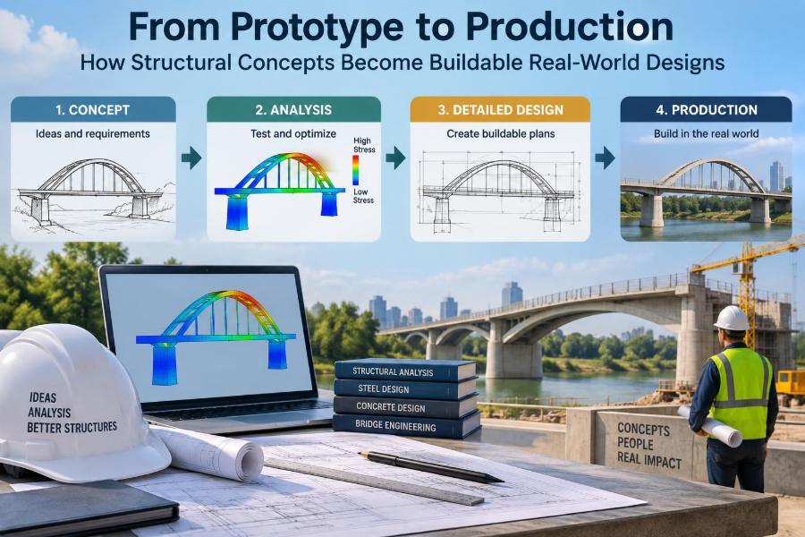

A structural idea can look convincing on a sketch, in a classroom model, or in a polished 3D render. A slender roof seems to float. A tower has a dramatic cantilever. A bridge deck follows a graceful curve across a valley.
Then the questions arrive: Where do the forces go? Can a crane place the pieces? Will a connection fit around the reinforcement? What happens when rain, heat, vibration, tolerances, and real people meet the concept?
That transition—from an appealing concept to a dependable physical asset—is where structural engineering becomes much more than calculation. It is a process of turning intent into load paths, details, sequences, inspections, and decisions that can survive the conditions of construction and service.
For students, this explains why a correct calculation is not yet a complete design. For working professionals, it is a reminder that buildability is not a late-stage check; it is a design input from the beginning.
🧭 A Concept Is Not Yet a Structure
A concept expresses a structural ambition: span a space without columns, create a transparent façade, reduce material, or make a building adaptable. At this stage, the geometry may be useful, but the structure is still only a hypothesis.
A buildable design must define a stable system, materials, members, supports, connections, construction sequence, and verification method. It also needs to accommodate architecture, building services, fabrication limits, site access, and maintenance.
The central shift is from “what should this look like?” to “how will this carry load, be assembled, and remain reliable?”
🎯 Start With the Performance Brief
Structural development begins with the performance the asset must deliver, not with a preferred beam or frame type. A warehouse, a hospital, a pedestrian bridge, and a long-span arena can all use steel or concrete, yet their governing priorities differ sharply.
The brief should establish the intended use, geometry, design life, environmental exposure, movement expectations, resilience objectives, and acceptable disruption during construction. It should also identify unusual loads early, such as suspended equipment, vehicle impact, crowds, blast requirements, or future vertical expansion.
- What spaces must remain column-free?
- Which elements may move, settle, or be replaced?
- What construction methods are realistically available?
- Which serviceability limits matter to occupants or equipment?
📐 Translate Architecture Into Structural Zones
Architectural plans describe rooms, openings, circulation, façade rhythm, and visual order. The structural engineer reads them differently: spans, support lines, discontinuities, load concentrations, and locations where lateral resistance can be concealed or expressed.
Early zoning often separates regular, repetitive areas from transfer zones, large openings, atria, plant rooms, and heavily loaded cores. This makes risk visible before a scheme becomes difficult to change.
A column grid is not merely a drafting pattern. It influences floor depth, foundation locations, parking layouts, façade modules, construction repetition, and cost.
⬇️ Establish a Continuous Load Path
Every load needs a credible route to the ground. Gravity loads typically travel from slabs or roof decking to beams, girders, columns or walls, foundations, and soil or rock. Lateral loads from wind or earthquakes require their own path through diaphragms, frames, braced bays, shear walls, collectors, and foundations.
Load paths should be traceable through every change in level, offset column, opening, and material transition. A transfer girder may solve an architectural conflict, but it concentrates forces and can introduce deflection, vibration, and connection challenges.
A helpful test is to ask: if one component receives a load, can the next component be named all the way to the foundation?
⚖️ Separate Strength From Serviceability
Strength checks address whether members and connections can resist factored actions without unacceptable failure. Serviceability addresses how the structure behaves in normal use: deflection, crack width, vibration, drift, settlement, ponding, or visual movement.
A floor may be strong enough yet still feel uncomfortable under footfall. A long beam may satisfy strength requirements while sagging enough to damage partitions or create façade problems. These outcomes are not cosmetic details; they affect function and durability.
Early concepts should therefore consider stiffness as well as capacity. Slenderness, support continuity, member depth, and material behavior often govern the first viable form.
🌬️ Identify the Loads That Actually Govern
Dead load is the permanent weight of structural and fixed building components. Imposed or live load arises from occupancy, storage, and movable items. But many projects are governed by less obvious actions: wind uplift, seismic drift, thermal restraint, snow accumulation, construction loads, soil pressure, or water pressure.
Load combinations and values are prescribed by the applicable codes and project criteria. Engineers must use the rules adopted for the project location and authority; a rule of thumb from another jurisdiction is not a substitute.
For unusual structures, physical behavior may be more decisive than familiar load categories. A canopy can be governed by uplift, a footbridge by vibration, and a retaining wall by drainage failure rather than concrete strength.
🏢 Choose a Primary Structural System
The primary system provides the main route for gravity and lateral forces. Common options include reinforced concrete frames and walls, structural steel frames, braced frames, timber panels, trusses, arches, shells, and composite systems.
Selection is a trade-off, not a material popularity contest. Concrete can provide mass, fire resistance, and robust wall systems, but may require curing time and careful control of shrinkage. Steel can achieve rapid erection and long spans, but connection design, fire protection, and corrosion exposure require attention. Timber can be light and renewable, but moisture management and connection behavior must be resolved.
| Design question | Likely structural consequence |
|---|---|
| Large clear span | Deeper girders, trusses, arches, or composite action may be needed. |
| High lateral demand | Walls, braced frames, moment frames, or a combined system may govern. |
| Restricted site access | Member size, delivery lengths, lifting weight, and assembly sequence become critical. |
| Fast enclosure required | Off-site fabrication and dry connections may be advantageous. |
🧱 Let Material Behavior Shape the Form
Materials perform differently in tension, compression, shear, bending, creep, shrinkage, and fire. Efficient structural forms take advantage of these tendencies instead of forcing material into an unfavorable role.
For example, a truss converts a deep bending problem into axial forces in its chords and diagonals. Reinforced concrete combines concrete’s compression capacity with steel reinforcement where tension is expected. A cable is efficient in tension but needs anchorage and a geometry that controls movement.
The aim is not to avoid bending at all costs. It is to understand what the selected form asks of the material and whether that demand is practical to deliver.
🧩 Size the System Before Refining Members
Early sizing establishes whether the overall scheme is plausible. Preliminary member depths, wall thicknesses, truss zones, and foundation footprints expose conflicts with ceiling heights, services, windows, and usable floor area.
This is not the same as final design. It is an iterative feasibility step based on structural mechanics, comparable projects, analysis models, and sound engineering judgment. Assumptions must be revisited as loads, spans, and geometry become fixed.
Starting with highly optimized individual members before the system is stable often creates rework. A well-proportioned scheme is easier to analyze, detail, fabricate, and adapt.
🖥️ Use Analysis Models With Engineering Judgment
Digital models can rapidly evaluate many load cases and member forces, but their output is only as trustworthy as the assumptions behind it. Support conditions, connection stiffness, diaphragm behavior, load distribution, releases, mesh density, and soil springs can change results substantially.
A model does not automatically know whether a slab can act as a diaphragm around large openings or whether a nominally pinned steel connection will develop meaningful stiffness. These are engineering decisions.
- Check equilibrium: do reactions reasonably match applied loads?
- Check deformation shapes: do they make physical sense?
- Check simplified hand calculations for critical members.
- Check whether loads can transfer where the model assumes they do.
🔄 Coordinate the Lateral System Early
Gravity framing and lateral stability are related but distinct. A building can have well-sized columns and beams yet remain laterally inefficient if its walls or braces are poorly placed.
Symmetry, stiffness distribution, diaphragm continuity, and foundation restraint influence how a structure responds to wind and seismic actions. An eccentric core or irregular plan can produce torsional response, meaning the building twists as well as translates.
Architectural changes such as removing a wall for an opening or shifting a core can fundamentally alter the lateral system. These choices should be reviewed before layouts are treated as final.
🔗 Connections Turn Members Into a System
Members do not act alone. Their connections determine how forces cross joints, whether rotation is allowed, how erection occurs, and how tolerances are accommodated.
A steel beam connection may transfer shear only, or it may need to transfer moment, axial force, and continuity effects. A precast concrete joint needs reliable bearing, reinforcement continuity where required, grouting, and erection stability. Timber connections require careful consideration of fastener layout, splitting, moisture movement, and fire protection.
Connection design should begin with force flow, not with a standard detail copied into a different situation.
🧷 Detail for Force Transfer, Not Just Geometry
A detail can look neat in elevation while concealing a serious force-transfer problem. Reinforcement may be impossible to place, a weld may be inaccessible, or bolts may clash with stiffeners and adjacent members.
Good detailing answers practical questions: where does bearing occur, how is shear transferred, what restrains buckling, what length is needed for development or anchorage, and how are local stresses spread into the supporting material?
Congested regions deserve special attention. Beam-column joints, transfer zones, wall couplers, anchor plates, and heavily loaded supports often control constructability more than ordinary repetitive bays.
🏗️ Design the Construction Sequence
The completed structure is not the only structure that matters. Temporary states during lifting, casting, shoring removal, bracing installation, or partial loading can be more vulnerable than the final condition.
A long steel truss may need temporary bracing before its roof diaphragm is complete. A concrete frame may carry loads differently before it reaches the intended strength. Precast elements may be stable only after connections are completed.
Sequence should identify who is responsible for temporary works and how assumptions are communicated. Permanent design drawings alone may not describe every erection-stage risk.
🚧 Make Buildability a Design Criterion
Buildability means the design can be constructed safely, accurately, and economically using realistic labor, equipment, access, and inspection methods. It does not mean simplifying every detail; complex solutions can be appropriate when their value justifies the execution demands.
Consider a hypothetical rooftop transfer truss. It may work structurally, but the team must also test delivery length, crane reach, lifting points, splice locations, welding access, weather exposure, and the effect of erection tolerances on adjacent façade work.
Early conversations with contractors and fabricators often reveal these constraints while changes are still relatively inexpensive.
📏 Plan for Tolerances and Movement
No building component is placed with perfect precision. Fabricated steel, concrete formwork, foundations, cladding, and mechanical equipment each have permitted variations. Details must allow the expected tolerances without losing bearing, alignment, drainage, or connection capacity.
Structures also move after construction. Thermal expansion, concrete shrinkage and creep, foundation settlement, wind drift, and live-load deflection can accumulate at interfaces.
Movement joints, slotted holes, compressible materials, adjustable connections, and carefully located bearings are tools for managing movement. They are not signs of poor design; they are acknowledgments of real behavior.
🌧️ Address Durability at the Beginning
Durability is controlled by exposure and detailing as much as by nominal material strength. Water, chlorides, freeze-thaw cycles, industrial pollutants, ultraviolet exposure, and trapped moisture affect different systems in different ways.
For reinforced concrete, cover, crack control, drainage, and mix specification influence reinforcement protection. For steel, coating systems, galvanizing where appropriate, drainage, ventilation, and inspection access matter. For timber, keeping water out and allowing assemblies to dry are fundamental.
A detail that allows water to sit against a connection can shorten service life even if it has ample initial strength.
🔥 Integrate Fire Performance With the Structure
Fire design considers more than a material label. Heat can reduce steel strength and stiffness, cause spalling risks in some concrete conditions, or char timber at a predictable outer layer while the remaining section carries load.
Fire resistance may be provided through concrete cover, applied protection, encapsulation, sacrificial timber thickness, compartmentation, or active systems as required by the governing regulations and fire strategy. Connections and supports must be considered alongside primary members.
Architectural exposure goals should be coordinated early. Exposed steel may require a carefully selected protection approach, while exposed timber needs detailing that respects both fire and moisture behavior.
🔊 Control Vibration and Human Comfort
Occupants experience floors and bridges through motion, not through design calculations. Rhythmic walking, aerobics, machinery, and crowds can create noticeable vibration even when static deflection is modest.
The response depends on mass, stiffness, damping, span, support conditions, and excitation frequency. A lightweight long-span floor may need greater stiffness, altered framing, added mass, damping measures, or a change in use assumptions.
Comfort criteria vary by occupancy. A laboratory housing sensitive equipment and an ordinary storage platform should not be evaluated as if they have the same performance expectation.
🕳️ Treat Foundations as Part of the System
Foundations transfer structural actions into the ground, but soil and rock behavior is variable. The design relies on geotechnical information about bearing resistance, settlement, groundwater, excavation conditions, lateral resistance, and potential ground hazards.
A strong superstructure on unsuitable or poorly understood ground is not a complete solution. Differential settlement can damage finishes, services, cladding, and structural elements even when ultimate foundation capacity has not been exceeded.
Structural and geotechnical engineers need to align assumptions about loads, movement limits, foundation type, and construction effects such as dewatering or adjacent excavation.
🧰 Coordinate Openings and Building Services
Mechanical, electrical, plumbing, fire protection, and data systems all need routes through the building. Late service penetrations through beams, slabs, walls, or braces can remove critical material or compromise fire and acoustic assemblies.
Coordination is easiest when structural depth zones and service corridors are identified early. Openings can then be framed, reinforced, or located away from highly stressed regions.
There is no universal rule that services must always yield to structure or the reverse. The right solution depends on performance, maintenance access, spatial priorities, and the cost of alternatives.
🧪 Prototype the Uncertain Parts
Not every project needs a physical prototype, but unfamiliar, highly repetitive, or high-risk details can benefit from mock-ups, trial assemblies, test lifts, or fabrication reviews. These activities reveal practical issues that drawings may not expose.
A façade support mock-up can test adjustment range and waterproofing interfaces. A complex reinforcement cage can confirm that bars, couplers, embeds, and concrete placement space are compatible. A full-scale connection trial may clarify installation sequence.
Testing and prototyping do not replace design checks. They reduce uncertainty about execution and provide feedback for improving the final detail.
✅ Design for Inspection and Quality Control
A design becomes dependable only when its critical requirements can be verified. If a weld cannot be accessed, a reinforcement lap cannot be seen before concrete is placed, or a hidden drainage path cannot be checked, quality assurance becomes difficult.
Drawings and specifications should identify hold points, material requirements, testing needs, inspection access, and acceptance criteria. The level of control should match the consequence and complexity of the work.
Clear documentation also helps resolve site questions. Ambiguous sketches invite assumptions, and assumptions at critical connections can become defects.
🗣️ Use Coordination as a Technical Tool
Coordination meetings are not merely administrative. They are where structural intent meets construction reality. The engineer may learn that a proposed splice cannot be lifted, while the architect may see that a minor ceiling adjustment eliminates a costly transfer beam.
Useful coordination is specific: identify interfaces, state assumptions, assign decisions, and record changes. Shared models can help visualize clashes, but they do not eliminate the need for people to understand load paths and responsibilities.
When disciplines communicate early, compromises can be deliberate rather than accidental.
💰 Understand Cost Beyond Material Quantity
A lighter structure is not automatically less expensive. Fabrication complexity, number of connections, temporary works, erection time, access restrictions, fire protection, finishes, and future maintenance can outweigh a reduction in tonnage or concrete volume.
Conversely, a slightly heavier but repetitive framing scheme may be easier to procure and install. Cost decisions should be assessed across the relevant project priorities, including programme, risk, embodied impacts, and operational needs—not only initial material mass.
Value engineering is most useful when it preserves required performance while removing unnecessary complexity. It is not simply a late reduction in member sizes.
♻️ Consider Adaptability and Whole-Life Effects
Buildable design also considers what happens after handover. Can equipment be replaced? Can the floor support a change of use? Are drainage routes maintainable? Can a bolted steel member be modified more readily than a monolithic element, and is that flexibility actually valuable?
Material selection affects repairability, disassembly, reuse potential, and maintenance planning. These questions do not always produce a single preferred system, but they prevent short-term convenience from becoming long-term constraint.
Designing for adaptation may include spare capacity, accessible connections, rational grids, or clearly documented load limits. Each strategy must be justified against cost and project needs.
⚠️ Recognize Common Concept-to-Construction Failures
Many avoidable problems begin as reasonable-looking decisions that were never tested against the next stage of work. Typical warning signs include:
- Columns that do not align through several floors without a clear transfer strategy.
- Bracing or shear walls placed where doors, glazing, or services later need to pass.
- Connections drawn without sufficient access for bolts, welding, or inspection.
- Member depths selected without allowing for deflection, camber, or service zones.
- Foundation assumptions made before adequate ground information is available.
- Temporary stability left undefined because the final structure appears stable.
These are not merely coordination errors. They can alter safety, programme, cost, and the behavior of the finished asset.
🛠️ Apply a Practical Design Workflow
A disciplined workflow keeps the concept connected to evidence as the design develops. The exact deliverables vary by project, but the logic is consistent.
- Define performance requirements, constraints, and governing codes.
- Map gravity and lateral load paths with the architectural layout.
- Compare viable structural systems and preliminary proportions.
- Model, calculate, and independently sense-check key behavior.
- Coordinate foundations, services, fire, façade, and construction sequence.
- Develop connection concepts and representative critical details.
- Review buildability, tolerances, durability, inspection, and maintenance.
- Update drawings, specifications, assumptions, and risk items as decisions change.
This is iterative rather than strictly linear. A detail issue can require a system change, and a construction constraint can reshape the original concept.
📚 What Students Can Practice Now
Students often encounter structural analysis as a set of idealized supports and loads. Those fundamentals matter, but design skill grows when each calculation is connected to a physical question.
When studying a beam, sketch its support, connection, load source, likely deflected shape, and construction method. When choosing a truss, ask how the members meet, how it is braced out of plane, and how it reaches the site.
Develop the habit of drawing load paths by hand before relying on software. It builds intuition that remains useful when models become complex.
👷 What Practitioners Should Keep Asking
Experience does not remove uncertainty; it helps engineers ask better questions earlier. A practical review can return repeatedly to a few fundamentals: Is the load path continuous? Does the detail match the analysis assumption? Can it be built and inspected? What changes in temporary conditions? What happens at interfaces?
Peer review is particularly valuable for unusual systems, high-consequence elements, and details that concentrate many demands. The purpose is not to find fault with a designer, but to expose assumptions before they become embedded in work.
Good structural practice combines calculation, observation, communication, and humility about what remains uncertain until construction and operation provide feedback.
🌉 The Core Principle: Design the Entire Journey
Structural concepts become real-world designs when the engineer treats form, forces, materials, connections, construction, and use as one connected problem. A striking idea earns its place by remaining coherent through every stage.
The best solution is rarely the one with the fewest members or the most dramatic rendering. It is the one that delivers the intended space while providing understandable load paths, appropriate performance, practical assembly, and durable service.
Buildable structural design is the discipline of making every important assumption physically credible—from the first line on paper to the structure’s long-term life.
A successful structure is not simply calculated into existence; it is conceived, detailed, built, checked, and maintained as a continuous chain of engineering decisions. 🏗️📐🔩