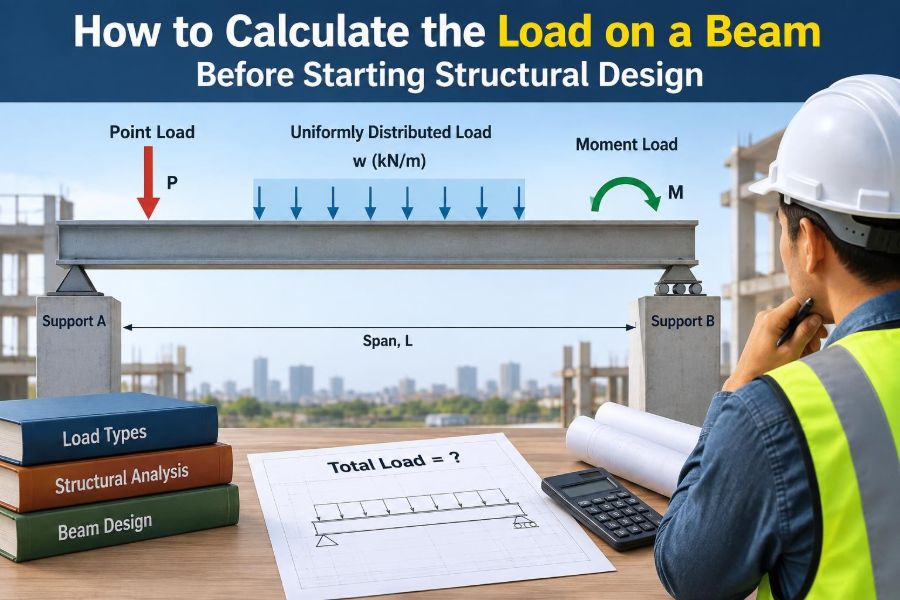

A beam can look deceptively simple: a timber member over a window, a steel girder carrying a floor, or a reinforced-concrete lintel above a garage opening. Yet before anyone selects its size, reinforcement, or connection details, one question must be answered carefully: what must it carry?
Getting the load wrong can make an otherwise elegant calculation meaningless. An undersized beam may deflect enough to crack finishes or damage partitions; an overly conservative assumption can add unnecessary depth, cost, and embodied carbon.
For students, beam loading is where free-body diagrams become a practical design tool. For working professionals, it is a repeatable process of interpreting drawings, tracing load paths, applying governing code requirements, and documenting assumptions.
The arithmetic is often straightforward. The engineering judgment lies in deciding which loads belong on the beam, where they act, which combinations govern, and what information is still uncertain.
🧭 Start with the design question
“Calculate the load on a beam” can mean several different things. It may mean the service load for checking deflection, the factored design load for checking strength, or the reactions needed to design columns and foundations below.
State the purpose before calculating. A preliminary sizing exercise may use approximate tributary areas, while final design requires verified geometry, material densities, occupancy data, code-prescribed load combinations, and a defined structural system.
🏗️ Understand what a beam actually does
A beam is a member designed primarily to resist loads transverse to its length. Those loads create internal shear forces and bending moments; depending on restraint and loading, they may also create torsion, axial force, or lateral instability concerns.
Load does not simply “sit” on a beam. It travels through floor slabs, joists, walls, framing connections, and supports. The beam is one link in that chain, so its calculation starts by understanding the whole load path.
🔗 Trace the complete load path
Sketch the route from the point where a load is applied to the ground. For a typical floor, occupants and furniture load the floor finish and slab or decking; that system transfers load to joists; joists transfer reactions to a girder; the girder transfers reactions to columns or bearing walls; those supports transfer load to foundations.
A beam may support another beam, a masonry wall, roof trusses, or a cantilevered balcony. Each case changes both the size and the form of loading. Never assume a floor load is the only load because the beam appears in a floor framing plan.
📐 Confirm span and support conditions
The span used in analysis must represent the actual support arrangement. A simply supported beam, a continuous beam over several supports, and a cantilever all produce very different moments under identical loading.
Clarify whether dimensions are center-to-center of supports, clear span, or face-to-face bearing length. Design standards and material specifications may define effective span differently, particularly for reinforced concrete and masonry construction.
Also identify whether connections provide moment restraint in reality. Calling a beam “fixed” merely because it meets a column can dramatically understate positive midspan moment if the connection was not designed to develop rotational restraint.
🗺️ Read plans, sections, and details together
Plans show where members occur, but sections often reveal what they support. A beam labeled on a plan may carry a wall above, a change in floor level, a roof reaction, or an edge condition that is invisible in plan view.
Review architectural, structural, and relevant services drawings together. Openings for ducts, offsets in framing, or concentrated plant loads can alter the structural arrangement. When documents conflict, record the issue rather than silently choosing the more convenient interpretation.
📦 Separate dead loads from live loads
Dead load is permanent load: the self-weight of the beam and fixed construction such as slabs, finishes, ceilings, permanent partitions where applicable, roofing, and fixed equipment. Its magnitude can generally be estimated from dimensions and material unit weights.
Live load, often called imposed load, comes from use and occupancy: people, movable furniture, stored items, and maintenance activity. It is generally obtained from the governing building code for the room or occupancy in question.
This distinction matters because codes usually apply different load factors and reduction rules to permanent and variable actions.
🧱 Calculate the beam’s self-weight
The beam carries itself. For a prismatic member, calculate self-weight as cross-sectional area multiplied by material unit weight. The result is normally a line load, such as kN/m or lb/ft.
For example, a hypothetical reinforced-concrete beam 300 mm wide by 500 mm deep has a gross area of 0.15 m². Multiplying by the applicable concrete unit weight gives its self-weight per metre. Use the density specified by the project or code, especially where lightweight concrete is proposed.
For preliminary steel design, the selected section’s published mass per unit length is used. Since section selection may change, self-weight should be updated after sizing rather than left as an early estimate.
🧩 Account for permanent construction above
Floor assemblies frequently contribute more load than the beam itself. Consider structural slabs, metal deck, screeds, tiles, raised floors, ceiling systems, roofing layers, insulation, waterproofing, and fixed services where they are supported by the framing.
Convert each layer into an area load by multiplying thickness by unit weight, then add the components. A 100 mm layer is not automatically “light”; the material matters. Dense finishes, topping slabs, and masonry elements can be significant.
Use measured or specified thicknesses where available. Generic allowances are useful at concept stage but should not replace confirmed build-ups at final design.
🧍 Select the correct occupancy load
Live load depends on use, not merely room name. An office, corridor, residential room, library stack area, storage room, assembly space, and equipment room can have substantially different prescribed loads.
Check the governing jurisdiction’s current code and the project’s stated occupancy classification. If use is not settled, identify the assumption and discuss whether a more demanding future use should be allowed for. Designing a floor for the wrong occupancy cannot be corrected by careful arithmetic.
🌧️ Include roof, snow, rain, and maintenance loads
A roof beam may carry permanent roofing load plus variable environmental actions. Depending on location and roof geometry, these can include snow accumulation, rain ponding, wind-related effects, maintenance loads, and loads from rooftop equipment.
Snow does not always act uniformly. Drifts can form against taller walls, parapets, roof steps, and mechanical units. Rainwater can also become more serious if deflection creates a low point that retains water, producing a load-deflection interaction that requires careful assessment.
Environmental loading is code- and site-specific. Do not import values from a project in another region without checking the applicable requirements.
🌬️ Recognize when wind creates beam actions
Wind is often associated with columns, bracing, and cladding, but beams can also be affected. Spandrel beams, canopy beams, roof edge members, and members supporting wall panels may receive wind pressure or suction through their tributary area.
Wind may act upward as uplift rather than downward gravity load. That reversal can govern connection design, bearing details, and continuity reinforcement even when gravity bending is modest.
🏢 Treat walls as line loads, not floor loads
A wall directly over a beam normally imposes a line load. Calculate it from wall thickness, height, material unit weight, finishes, and any supported construction above it.
For a masonry or concrete wall, this can be substantial. For a light framed partition, it may be smaller but still relevant, particularly if it runs parallel to a beam and is supported continuously by it.
Where partition locations are movable or not fixed, codes may permit an allowance distributed across the floor rather than modeling each partition. That decision depends on the applicable rules and the structural system.
🎯 Identify concentrated loads
A point load acts at a localized position. Examples include a column reaction framing onto a transfer beam, a roof truss reaction, a heavy machine support, a stair stringer connection, or a reaction from a secondary beam.
Point loads are especially influential when near midspan, where they can create high bending moment, or near supports, where they can create high shear. Their exact location matters, so obtain dimensions rather than estimating from an uncluttered architectural plan.
📏 Use tributary area for floor load transfer
For uniform floor area loads, the common first step is finding the beam’s tributary area: the area of floor whose load is delivered to that beam. A simple rule is to extend halfway to the adjacent parallel supports on each side.
If a beam supports joists spanning perpendicular to it, its tributary width is commonly half the joist span from one side plus half from the other. Multiply this width by the floor area load to obtain an equivalent line load on the beam.
This method works when the framing geometry and load transfer are clear. Irregular panels, transfer systems, two-way slabs, and discontinuous framing may require a more refined analysis.
↔️ Convert area loads into line loads
Area loads are expressed in force per area, such as kN/m² or psf. Beam analysis normally needs line loads, such as kN/m or lb/ft. The conversion is:
line load = area load × tributary widthFor a hypothetical floor load of 5 kN/m² and a tributary width of 3 m, the corresponding beam load is 15 kN/m. Add the beam’s self-weight and any wall or other line loads separately.
Keep units visible at every step. Unit errors are among the quickest ways to produce a plausible-looking but incorrect answer.
📊 Keep a load schedule before combining anything
A simple load schedule makes assumptions auditable and reduces omissions. List each source, its classification, original units, conversion method, resulting beam load, and where it acts.
| Load source | Typical form at beam | Key check |
|---|---|---|
| Slab and finishes | Uniform line load | Correct tributary width |
| Beam self-weight | Uniform line load | Final member size used |
| Wall above | Line load or point load | Actual bearing path |
| Secondary framing | Point reactions or distributed load | Member spacing and reactions |
| Equipment | Point or patch load | Location and dynamic effects |
Do not combine dead and live loads too early. Retaining separate categories is necessary for load combinations and serviceability checks.
⚖️ Distinguish service loads from factored loads
Service loads are generally unfactored or differently combined loads used for performance checks such as deflection, vibration, cracking, and sometimes bearing pressure. Factored loads are amplified combinations used to provide an appropriate reliability margin for strength design.
The exact factors and combinations depend on the design standard, jurisdiction, material, and design method. A familiar combination from one code must not be assumed valid for another project. Use the governing standard and its referenced loading provisions.
🧮 Build load combinations, not a single “maximum load”
Different actions are unlikely to reach their maxima at the same time. Load combinations reflect this by applying factors and companion-load rules to dead, live, snow, rain, wind, seismic, and other relevant actions.
One combination may govern positive bending, another support uplift, and another deflection. The governing result is not always the combination with the greatest total vertical load.
Prepare a concise combination table or use verified analysis software, then review which action actually controls each check.
📉 Draw the free-body diagram
A free-body diagram turns a load list into a structural model. Show the beam, support locations, spans, distributed loads, point loads, applied moments where relevant, and load directions.
For a uniformly loaded simple span, a distributed load can be represented by a single resultant equal to load intensity times span, acting at the center of that loaded length. This helps when checking reactions by hand.
A clear sketch catches errors that a spreadsheet can hide: a load on the wrong span, a missing overhang, a point reaction placed at midspan instead of at a framing line, or uplift entered with the wrong sign.
🧷 Calculate support reactions first
Before calculating shear and moment, solve the reactions. For a statically determinate beam, use equilibrium: the sum of vertical forces is zero and the sum of moments about any point is zero.
For example, a uniformly loaded simply supported beam with load intensity w over span L has total load wL. Each support reaction is wL/2 when loading and geometry are symmetric.
Reactions are not merely intermediate results. They become design loads for columns, walls, connections, and foundations.
📈 Convert loading into shear and bending moment
Shear force describes the internal vertical force across a section; bending moment describes the internal turning effect. Their diagrams show where the beam is most highly demanded.
For a simply supported beam with a full-span uniform load, the maximum shear occurs at the supports and the maximum positive moment occurs near midspan. Common textbook formulas are useful only when their support and loading assumptions match the actual beam.
Simply supported beam, uniform load w over span L:
maximum shear = wL/2
maximum moment = wL²/8
For point loads, partial loads, cantilevers, or continuous spans, calculate or model the actual load arrangement rather than forcing it into a uniform-load formula.
🔄 Consider continuous-beam behavior carefully
When a beam continues over intermediate supports, moments redistribute compared with a simple span. Negative moments can develop over supports, while positive moments in spans may reduce.
This can be structurally efficient, but it creates demands that must be detailed and resisted at supports. Reinforced concrete needs appropriate top reinforcement; steel connections and framing continuity must be capable of developing the assumed behavior.
If continuity is uncertain because of construction joints, simple connections, or support flexibility, a conservative simple-span assumption may be appropriate for preliminary work. Final assumptions must be consistent with the detailing.
🌀 Check torsion and eccentricity
Loads should ideally pass through the beam’s intended load path. When a slab edge, wall, bracket, or supported member bears off-center, the beam can experience torsion in addition to bending and shear.
A beam supporting an edge wall with the wall located to one side of its centerline is a common example. Torsion can be critical in reinforced concrete, where it requires specific closed reinforcement and compatibility with the surrounding framing.
Do not erase eccentricity simply by drawing the load at the beam centerline. Investigate whether diaphragm action, slab behavior, or framing provides an alternative load path before simplifying.
📉 Check deflection under realistic service loading
A beam can be strong enough against collapse yet perform poorly in service. Excessive deflection can crack brittle finishes, misalign doors, pond water, disturb drainage, and create noticeable floor movement.
Deflection depends on stiffness as well as load. Span, member depth, material modulus, cracking in concrete, connection behavior, and long-term effects all matter. Long-term deflection in concrete and timber requires particular attention because creep and moisture-related behavior can increase movement over time.
Use the deflection limits and calculation method required by the governing standard and project criteria. A strength-only beam design is incomplete.
🎵 Do not overlook vibration
Floor vibration is a serviceability issue distinct from static deflection. A light, long-span floor can feel springy even if its calculated deflection is within a conventional limit.
Occupant comfort depends on factors such as natural frequency, damping, mass, walking excitation, and floor layout. Gyms, offices, residential spaces, and areas with rhythmic activity may need project-specific evaluation rather than a simple load calculation.
🧱 Check local bearing and web effects
A concentrated reaction can cause local damage even when global bending capacity is adequate. Examples include crushing at a bearing, web crippling in a steel beam, local flange bending, concrete splitting, or excessive compression perpendicular to grain in timber.
Support lengths, bearing plates, stiffeners, load-spreading details, and reinforcement may be needed. The load calculation must identify not only the total reaction but also the contact geometry through which it enters the member.
🛠️ Include construction-stage loading
The final building is not the only structural condition. During construction, fresh concrete, formwork, stacked materials, equipment, incomplete bracing, and temporary supports can load members in ways not present in the completed structure.
A composite beam may carry wet concrete before composite action develops. A precast member may have different support conditions during lifting and erection. Construction sequencing should be reviewed when it affects the beam’s demand or stability.
💻 Use software as a checker, not a substitute for judgment
Structural analysis software is valuable for multi-span beams, irregular loading, and three-dimensional systems. It can rapidly generate reactions, force diagrams, deflections, and combinations.
But software faithfully analyzes the model entered, not the building intended. Verify member releases, support stiffness, load directions, tributary widths, self-weight settings, units, and combination definitions. A hand estimate of total load and likely reactions is an essential reasonableness check.
⚠️ Avoid the most common loading mistakes
- Using architectural dimensions without confirming the structural support lines.
- Forgetting beam self-weight after changing the member size.
- Applying a slab area load directly as a beam line load without tributary-width conversion.
- Double-counting slab load when reactions from secondary members already include it.
- Ignoring walls, equipment, façade reactions, or roof drift loads.
- Assuming fixed supports or continuity without a connection detail that provides it.
- Mixing service and factored loads in one undocumented total.
- Using a formula outside the loading and support case for which it was derived.
Most of these errors are prevented by a load path sketch, a transparent schedule, and a final independent review.
📝 Document assumptions and unresolved items
Every beam calculation should communicate its basis. Identify drawings used, assumed material weights, occupancy classification, tributary widths, support conditions, load locations, code edition, and applicable combinations.
Flag unresolved information explicitly: “wall weight to be confirmed,” “equipment reaction pending supplier data,” or “connection assumed simple pending detail.” This is not a weakness; it makes coordination possible and prevents provisional assumptions from becoming invisible final decisions.
🔍 Work through a compact hypothetical example
Consider a simply supported interior beam with a 6 m span. It supports floor joists framing into both sides, with a total tributary width of 4 m. Suppose the estimated permanent floor load excluding the beam is 4 kN/m² and the specified live load is 3 kN/m².
The permanent floor line load is 4 × 4 = 16 kN/m. The live line load is 3 × 4 = 12 kN/m. If a preliminary estimate of beam self-weight is 2 kN/m, the service gravity total is 30 kN/m, while dead and live portions remain separately identified.
For the simple-span service case, total load is 30 × 6 = 180 kN, giving approximately 90 kN reaction at each support. The uniform-load moment expression gives a preliminary midspan service moment of 30 × 6² / 8 = 135 kN·m.
This is an illustration of load conversion and equilibrium only. Final design would use verified dimensions, required load combinations, material-specific resistance checks, deflection criteria, connection and bearing design, and the governing local code.
✅ Final principle: calculate load before sizing resistance
Beam design begins with a credible description of what reaches the member. Establish the structural arrangement, trace each load path, calculate permanent and variable actions separately, convert loads into the correct form, apply the required combinations, and analyze the actual support condition.
The resulting shear, moment, reaction, torsion, and deflection demands are the inputs to member design—not afterthoughts. A sophisticated material design cannot compensate for loads that were omitted, misplaced, double-counted, or combined incorrectly.
A reliable beam calculation is built from a reliable load path: know what is supported, where the load enters, how it travels, and which design situation governs. With that foundation, sizing and detailing become defensible engineering decisions rather than guesses. 🏗️📐✅