
A floor that feels bouncy beneath foot traffic, a beam with a noticeable sag, or a cracked ceiling below a long-span room can make occupants understandably uneasy. Yet these observations do not automatically mean a structure is close to collapse.
Often, the problem is excessive deflection: movement or deformation that is larger than the structure, its finishes, or its users can reasonably tolerate. A member may still have adequate strength against failure while performing poorly in service.
That distinction matters. Strengthening a member without first understanding why it deflects can waste money, shift loads into an unprepared part of the building, or conceal a more serious deterioration problem.
Engineers approach deflection repair as an investigation, not a catalogue of fixes. They establish what is moving, why it is moving, whether the movement is active, and which intervention improves performance without creating new risks.
📐 What Deflection Actually Means
Deflection is the displacement of a structural member under load. A beam commonly deflects downward between its supports; a cantilever rotates and drops at its free end; a column may move sideways under wind or eccentric loading.
Some deflection is expected. Buildings are not perfectly rigid, and a structure that flexes modestly can be entirely safe. The engineering question is whether the amount, location, rate, and consequences of movement remain acceptable.
⚖️ Strength and Stiffness Are Different Properties
Strength describes resistance to yielding, crushing, buckling, fracture, or other failure modes. Stiffness describes resistance to deformation. A member can be strong enough not to break but flexible enough to crack finishes, pond water, disturb equipment, or feel uncomfortable.
For a simple beam, deflection is influenced by load, span, support condition, elastic modulus, and moment of inertia. In simplified form, greater span and load increase movement, while higher material stiffness and a deeper effective section reduce it.
This is why adding a small amount of material in the wrong place may add strength with little effect on serviceability.
👀 Recognizing the Signs in Real Buildings
Visible sagging is the obvious sign, but it is not the only one. A practical inspection also looks for consequences of differential movement: cracks, gaps, sticking doors, sloping floors, separated trim, damaged partitions, and misaligned cladding.
- Cracks in brittle finishes may reflect beam movement, shrinkage, settlement, or temperature change.
- Ceiling cracks below a floor can indicate movement, but their direction and location matter.
- A floor that vibrates under walking may be governed by dynamic comfort rather than static deflection alone.
- Water collecting on a nominally sloped roof can reveal long-term roof framing deflection.
Observations are clues, not diagnoses. Similar symptoms can arise from very different mechanisms.
🧭 Start with the Structural Load Path
Before considering reinforcement, engineers trace the load path: deck or slab to joists, joists to beams, beams to columns or walls, and then to foundations. Every proposed strengthening measure must fit this route.
For example, a new post under a sagging beam may reduce its span dramatically. But that post also creates a concentrated reaction at the floor or footing below. If the supporting structure cannot accept it, the apparent solution merely relocates the problem.
🗂️ Gather Evidence Before Designing a Fix
Good assessment begins with drawings, past alterations, construction records where available, and a measured site survey. Engineers confirm member dimensions, spans, support details, materials, visible defects, and the actual use of the space.
Useful evidence may include level readings, crack maps, photographs, moisture observations, reinforcement scanning for concrete, or probes that reveal concealed framing. The scope should be proportionate: an accessible steel beam needs a different investigation from a post-tensioned slab.
📏 Measure the Movement, Not Just the Impression
Human perception is useful but unreliable. A floor can feel steep because a wall is out of plumb; a beam can look bowed because adjacent finishes are uneven. Measured elevations establish the geometry that calculations and decisions require.
Laser levels, total stations, string lines, straightedges, and carefully selected reference points can document relative displacement. Repeating measurements over time helps separate an old, stable sag from movement that is still progressing.
Measurements should account for temperature, access limitations, and uncertain original geometry. In an older building, the original member may never have been perfectly straight.
⏳ Separate Immediate, Long-Term, and Active Deflection
Loads applied to a member cause immediate elastic deformation. Concrete and timber may also develop significant time-dependent movement through creep, shrinkage, moisture change, or sustained loading. Connections can settle or slip over time.
An old deflection that has stabilized may primarily require a serviceability decision. Active movement requires a search for its driver: added load, corrosion, decay, foundation movement, leaking water, altered supports, or ongoing construction nearby.
Repairing a finish while active structural movement continues is rarely durable.
🧮 Check the Actual Loading
Many deflection problems begin after a change in use. Dense storage, library stacks, heavy mechanical units, rooftop equipment, planters, suspended ceilings, and new partitions can impose loads absent from the original design assumptions.
Dead load is the permanent weight of construction and fixed equipment. Live load varies with occupancy and use. Engineers also consider snow, rainwater, wind, construction loads, and localized point loads where relevant.
A load take-down should reflect what is truly supported by the member, not simply a generic description of the room above it.
📚 Use Deflection Criteria with Judgment
Design standards commonly provide deflection limits expressed as a fraction of span, but the applicable criterion depends on material, member type, occupancy, finishes, roof drainage, and the load being considered. A limit suitable for a bare industrial floor may not protect brittle partitions or sensitive equipment.
Code limits are not a universal line between safe and unsafe. They are serviceability benchmarks. An engineer must also consider the observed condition, the reliability of assumptions, occupant comfort, and the consequences of further movement.
🧱 Understand Why the Member Is Flexible
A member may be undersized, but geometry is only one explanation. The problem can arise from a longer-than-assumed span, insufficient lateral restraint, connection rotation, reduced section from damage, composite action that was assumed but never achieved, or support settlement.
In flexure, material near the top and bottom of a beam contributes strongly to bending stiffness. This is one reason depth is so powerful: moving material farther from the neutral axis increases the section’s moment of inertia substantially.
🪵 Timber Members Need Moisture and Connection Checks
Timber stiffness depends on species, grade, grain direction, moisture condition, defects, and member orientation. Notches, holes, splits, insect damage, and fungal decay can materially change both capacity and stiffness.
Joists may also deflect because their bearing has crushed, hangers are inadequate, or bridging and blocking have failed. Simply sistering a joist without correcting a wet crawlspace or leaking roof can leave the underlying deterioration untouched.
🔩 Steel Members Can Lose Performance in Subtle Ways
Steel beams are generally stiff for their weight, but long spans, shallow profiles, connection flexibility, corrosion loss, and added loads can still produce unacceptable movement. A beam that lacks adequate lateral restraint may also be vulnerable to lateral-torsional buckling, a stability issue rather than merely a deflection issue.
Field welding, drilling, and heating require careful planning. Existing steel may have uncertain properties, coatings may create hazardous fumes, and nearby materials may be sensitive to heat or vibration.
🏛️ Concrete Deflection Is Often Time-Dependent
Reinforced concrete cracks in tension under normal service conditions. After cracking, stiffness decreases, and long-term creep under sustained load can increase deflection over years. Shrinkage, reinforcement quantity, slab depth, support restraint, and construction sequence all influence the outcome.
Concrete assessment may require locating reinforcement, evaluating deterioration, and understanding whether a slab behaves as one-way, two-way, or post-tensioned construction. Cutting or coring without that knowledge can be dangerous.
🧪 Rule Out Deterioration Before Adding Reinforcement
Corrosion, decay, chemical attack, fire damage, water intrusion, and repeated overloading can reduce an existing member’s effective section or damage its connections. Strengthening over degraded material may provide unreliable load transfer.
For example, a steel plate bolted to severely corroded steel cannot restore performance unless the remaining parent material can safely transfer forces. Likewise, a concrete overlay cannot compensate for active reinforcement corrosion without addressing the corrosion mechanism.
🪜 Reduce the Span with a New Support
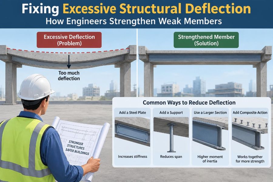
Adding a column, wall, hanger, or intermediate support can be one of the most efficient ways to reduce deflection because it shortens the effective span. For uniformly loaded simple beams, deflection changes very rapidly with span, so even a modest reduction can have a large effect.
The trade-off is architectural and structural. New supports affect circulation, foundations, fire protection, services, and load paths. They also need a carefully designed connection that transfers load gradually and predictably.
➕ Increase Member Depth Where Space Allows
Increasing depth is often the most direct stiffness solution. A deeper timber sister, built-up steel section, reinforced concrete haunch, or engineered wood member can reduce bending deformation more effectively than adding a thin plate near the neutral axis.
Depth may be limited by headroom, ceiling systems, doors, utilities, façade details, or fireproofing. A practical scheme balances structural efficiency with the building’s physical constraints.
🧷 Sistering and Built-Up Members
Sistering means installing an additional member alongside an existing one, common in timber floor repairs. It works only if the new member has adequate bearing and a connection system capable of sharing load with the original member.
Fasteners are not decorative. Their number, spacing, edge distances, slip behavior, and installation quality determine whether the pair acts together. A sister that is loosely attached may carry little of the existing gravity load until further deflection occurs.
🧲 Plate, Angle, and Channel Reinforcement
Steel plates, angles, channels, or tees can reinforce timber or steel members. Their effectiveness depends heavily on placement and force transfer. Reinforcement positioned farther from the neutral axis generally contributes more to bending stiffness, provided connections develop the required forces.
Bolted details are often attractive for occupied buildings because they avoid some welding constraints. However, bolt holes remove material, and a poor drilling pattern can weaken the member or miss concealed reinforcement and services.
🧱 Concrete Jacketing and Section Enlargement
Concrete jacketing enlarges a beam, column, or wall with new reinforced concrete. When properly detailed, it can improve strength, stiffness, confinement, and durability. Surface preparation, reinforcement development, shear transfer, and compatibility between old and new concrete are central to success.
It is not simply a matter of pouring more concrete around a member. The added weight, construction access, curing conditions, and altered dimensions can create practical limitations, especially in occupied structures.
🧵 Fiber-Reinforced Polymer Has Specific Uses
Fiber-reinforced polymer, often called FRP, uses high-strength fibers in a resin matrix bonded externally to concrete, masonry, timber, or sometimes steel. It can be thin, lightweight, and useful where added depth or weight is unacceptable.
FRP is not automatically a stiffness cure. Depending on the system and layout, it may provide substantial strength improvement while producing a more modest change in service-load deflection. Bond condition, substrate quality, fire exposure, ultraviolet protection, and detailing at ends must be assessed.
🔗 Connections Often Control the Outcome
Many strengthening concepts look effective on paper until the connection is examined. New material must receive load through bolts, welds, adhesives, bearing, shear connectors, anchors, or bearing seats. If that transfer is too flexible, the new reinforcement engages late or not at all.
Connections also concentrate stresses. A beam may be improved at midspan but overloaded near an end connection, or a new hanger may overload the supporting wall. Design must check the whole assembly.
🎯 Preloading and Jacking Require Restraint
Engineers may jack a sagging member before installing reinforcement or a new support. The purpose can be to restore elevations, close gaps, or ensure the new element participates in carrying existing load rather than only future load.
Jacking must be gradual, monitored, and based on a defined sequence. Lifting can crack finishes, bind doors, redistribute force into adjacent members, or damage brittle utilities. Full return to an original line is not always realistic or desirable.
🌊 Vibration Is Not the Same as Static Sag
A light floor can meet a static deflection criterion and still feel uncomfortable when people walk across it. This is a dynamic response influenced by natural frequency, damping, mass, footfall rhythm, and floor continuity.
Adding stiffness may help, but adding mass can sometimes change the response in less intuitive ways. Vibration assessment needs an appropriate dynamic model or field evaluation rather than a static beam calculation alone.
🏠 Protect Finishes, Drainage, and Building Function
Serviceability is about the building as a system. Deflection can crack gypsum board, distort glazing, open roofing laps, interfere with drains, misalign elevators, and disrupt equipment even where the primary member remains structurally adequate.
On low-slope roofs, ponding water deserves particular attention. Deflection can deepen a low area, accumulating more water and increasing load, which may cause additional deflection. This feedback mechanism should be evaluated rather than treated as an ordinary cosmetic issue.
🚧 Plan Construction Loads and Temporary Works
Strengthening work changes the structure before it improves it. Removing finishes, drilling holes, placing wet concrete, moving equipment, or temporarily releasing a connection may impose loads and conditions not present in normal service.
Temporary shoring, erection sequence, access routes, and worker safety should be designed as part of the intervention. A permanent retrofit can be sound while its installation sequence remains unsafe.
❌ Common Fixes That Miss the Real Problem
Several intuitive repairs fail because they address appearance rather than behavior:
- Filling cracks without determining whether movement is active.
- Adding a thin reinforcing plate where it contributes little stiffness.
- Installing a post without checking the floor and foundation below.
- Bolting new steel to a member without enough connectors to develop composite action.
- Leveling a floor with heavy topping without checking the added dead load.
- Using a generic span table after the building’s load path has changed.
The recurring mistake is treating a structural system as an isolated beam.
🧾 Document Assumptions and Final Conditions
Existing-building work always contains uncertainty. Clear documentation should record observed dimensions, hidden conditions that could not be verified, assumed material properties, loading assumptions, calculations, repair details, inspection points, and construction sequence.
After installation, photographs and measurements provide a useful baseline. They help owners monitor future movement and give later engineers a reliable record of what was changed.
🧰 Choose Repair, Reinforcement, or Replacement
Repair is appropriate when the member is fundamentally adequate but localized damage or a connection defect needs correction. Reinforcement is appropriate when the member can remain in place and a practical load path can be created. Replacement may be better when deterioration is widespread, geometry is fundamentally unsuitable, or extensive strengthening would be more disruptive than renewal.
The least invasive option is not always the best lifecycle choice. Durability, inspection access, fire protection, corrosion exposure, maintenance, and future adaptability all matter.
👷 Know When Specialist Input Is Essential
Structural alterations should be assessed and designed by a qualified engineer familiar with the relevant material and local requirements. This is particularly important for post-tensioned concrete, historic fabric, fire-damaged structures, heavily corroded steel, major cracking, foundation movement, and any member supporting multiple stories.
Urgent evaluation is appropriate where deflection is increasing, connections are visibly distressed, concrete is spalling, timber is severely decayed, a roof is ponding, or a member has been damaged by impact, fire, or unauthorized modification. Occupancy restrictions or temporary support may be warranted while the condition is assessed.
🧠 The Core Principle: Improve the Whole Structural System
Excessive deflection is solved most reliably by identifying the governing mechanism and improving the relevant part of the system: load, span, stiffness, support condition, connection behavior, or deterioration. The visible sag is the result, not necessarily the cause.
A successful strengthening design checks serviceability and safety together, establishes a complete load path, and considers how the work will be installed. It also accepts that some long-standing movement may remain even after the source is corrected.
The best retrofit is not the one that adds the most material; it is the one that creates a durable, well-connected, and verifiable path for forces while controlling future movement.
When engineers treat deflection as evidence of structural behavior rather than a cosmetic defect, they can select interventions that are safer, more efficient, and better suited to the building’s future use. 🏗️📏🔩