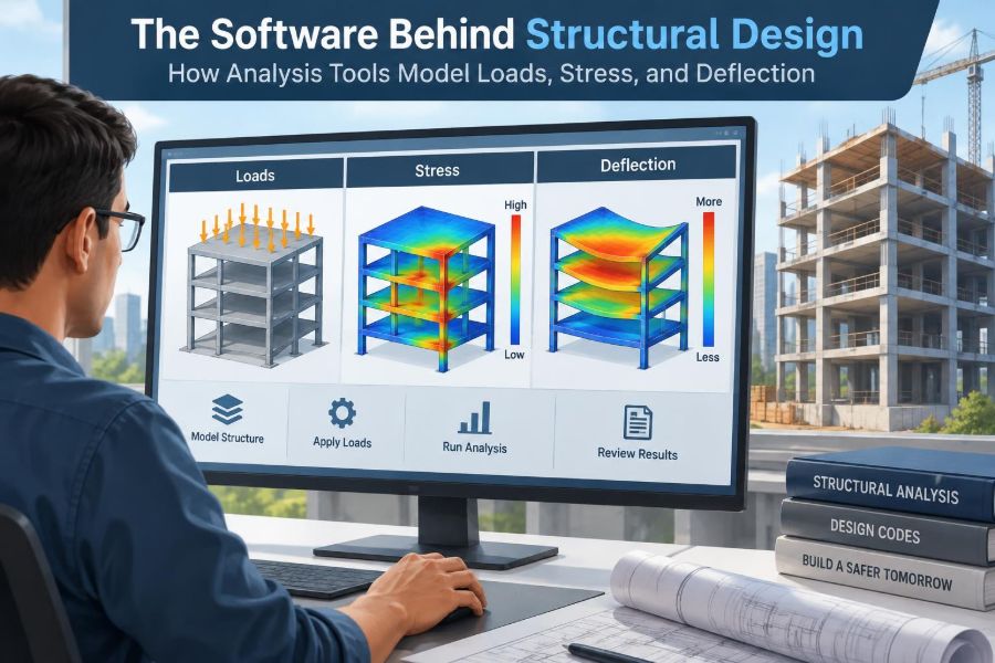

A structural engineer can stand beneath a long-span roof, look at a slender bridge pier, or walk through a new office floor and see more than concrete and steel. They see a system carrying weight, resisting movement, and directing forces safely to the ground.
Modern analysis software makes that invisible force system visible. Within minutes, a model can display bending-moment diagrams, deflected shapes, reactions at supports, and warning messages about members that may not meet selected design checks.
That speed is useful, but it can also create a dangerous illusion: that a colorful model is automatically a correct model. Software calculates exactly what it is told to calculate, including assumptions that may be incomplete, unsuitable, or simply wrong.
Understanding what happens behind the interface helps students learn structural behavior and helps practicing engineers review models with better judgment. The goal is not to replace engineering intuition with software; it is to use software as a disciplined extension of it.
🧭 What Structural Analysis Software Actually Does
Structural analysis software represents a building, bridge, tower, industrial frame, or other structure as a mathematical model. It uses geometry, material properties, supports, connections, and loads to estimate how that system responds.
The primary results are usually internal actions and movements: axial force, shear force, bending moment, torsion, stress, rotation, and deflection. Design modules may then compare those actions with the capacity of a selected member and code-based design rules.
Analysis asks how a structure responds; design asks whether its members and connections are adequate. Many programs combine both tasks, but they remain different engineering questions.
🏢 Why a Physical Structure Must Become a Model
A real structure contains welds, bolts, cracks, construction tolerances, composite action, soil variability, and many other details. Modeling every physical feature exactly would be impractical and, in many cases, unnecessary.
Engineers therefore create an idealization: a simplified representation that preserves the behavior relevant to the decision at hand. A preliminary gravity model can be simple, while a long-span roof, irregular high-rise, or vibration-sensitive floor may need much richer detail.
The model is not the structure. It is a purposeful approximation of the structure, and its usefulness depends on whether its simplifications are appropriate.
📐 Geometry, Nodes, and Elements
Most structural models are assembled from nodes and elements. Nodes are points where members meet, loads are applied, supports are placed, or results are reported. Elements connect nodes and carry the mathematical description of structural behavior.
A beam element may represent a girder; a column element may represent a vertical steel or concrete member; a shell element can represent a slab, wall, or plate; and a solid element may be used for a complex three-dimensional region.
Choosing the right element type matters. A thin concrete wall treated as a line member may miss important in-plane or out-of-plane behavior, while modeling every ordinary beam with dense solid elements can make a model slow and harder to review.
🧩 Degrees of Freedom: The Motions a Model Allows
At each node, software defines possible movements called degrees of freedom. In a three-dimensional frame, these commonly include translation in three directions and rotation about three axes.
Supports and connections restrain some of those movements. A fixed support resists translation and rotation; a pin commonly restrains translation but permits rotation; a roller restrains movement in selected directions while allowing another direction of movement.
If a needed restraint is missing, the model can behave like a mechanism. If too many restraints are added, the structure can appear unrealistically stiff. Both errors alter forces as well as deflections.
🧱 Material Properties and Section Stiffness
Software cannot infer whether a member is steel, reinforced concrete, timber, aluminum, or masonry. The engineer supplies material properties such as elastic modulus, density, strength values, thermal behavior, and sometimes nonlinear constitutive data.
For a beam, stiffness depends not only on the material but also on cross-sectional geometry. The familiar product EI combines elastic modulus E and second moment of area I; a larger value generally means greater resistance to bending.
Section properties also affect torsion, shear deformation, and axial shortening. A model with the wrong member orientation or section assignment can yield plausible-looking diagrams that describe the wrong structure.
🪨 Supports and Boundary Conditions
Boundary conditions describe how the structure connects to its surroundings. They include foundations, bearings, soil springs, wall restraints, diaphragm constraints, and the stiffness of attached components.
A common early-model assumption is a perfectly fixed base. That may be reasonable for some situations, but real foundations and soils can rotate, settle, or translate. For tall, flexible, or heavily loaded systems, foundation flexibility can materially affect drift and force distribution.
Support reactions provide a basic check: the total vertical reaction should balance the applied vertical load for a stable static model, subject to the chosen sign convention and load cases.
🔗 Connections Are Not Always Perfect Pins or Fixes
Textbook diagrams often classify connections as pinned or fixed. Real connections occupy a range between those ideals. A bolted end-plate connection, for example, may have finite rotational stiffness rather than zero or infinite stiffness.
Software can represent this behavior using releases, partial-fixity connections, springs, or specialized link elements. The appropriate choice depends on the connection detail and on whether its flexibility changes the overall structural response.
Assuming every beam-to-column joint is rigid can reduce predicted deflection but may introduce moments that the actual connection was not detailed to resist. Assuming every connection is pinned can overlook frame action and lateral stiffness.
🌧️ Load Cases: Separate the Actions First
A load case is a defined set of actions applied to the model. Common gravity load cases include self-weight, superimposed dead load, occupancy live load, roof load, and equipment load. Lateral cases may include wind, seismic effects, earth pressure, water pressure, or crane actions.
Keeping load cases separate makes the model understandable. It lets engineers see which loading produces a particular response and makes later changes easier to trace.
Self-weight is often generated automatically from material density and member volume. That convenience requires checking that density assignments, element dimensions, and self-weight multipliers are correct.
🧳 Load Paths: Following Force to the Ground
A load path is the route by which force travels from where it is applied to the supporting ground. On a typical floor, load may pass from slab to beams, from beams to girders, from girders to columns or walls, and then through foundations into soil.
Analysis software distributes load according to the stiffness and connectivity represented in the model. It does not know the intended load path unless the model contains the components and connections that make that path possible.
A useful review question is simple: if a particular beam, wall, or support were removed from the drawing, where would its load go? If the answer is unclear physically, the model deserves closer inspection.
➕ Load Combinations and Design Situations
Structures are checked under combinations of load cases because maximum effects rarely arise from one action alone. Design standards prescribe combinations for strength, stability, serviceability, and sometimes special events, with factors that depend on the governing code and design situation.
Strength combinations address safety against collapse or loss of resistance. Serviceability combinations focus on behavior in normal use, such as floor deflection, crack control, building drift, or vibration-related comfort.
Software can generate many combinations automatically, but the engineer must confirm that the selected code, occupancy assumptions, lateral-load directions, and relevant cases are appropriate for the project.
⚖️ Equilibrium: The First Non-Negotiable Check
For a stable structure in static equilibrium, the applied forces and moments must balance the reactions and internal forces. This is one of the most powerful model-review principles because it is independent of software brand or graphical polish.
Reaction summaries can reveal omitted load, duplicated load, accidental support conditions, or a disconnected part of the model. They should be compared with quick hand estimates, especially for total gravity load and major lateral reactions.
Equilibrium alone does not prove a model is correct. A model can balance perfectly while using an incorrect stiffness, unrealistic release, or missing load path. It is necessary, not sufficient.
🧮 The Stiffness Matrix Behind the Results
In linear elastic analysis, each element contributes stiffness relationships to a larger system known as the global stiffness matrix. In simplified form, the program solves a relationship often written as K u = F, where K represents stiffness, u displacement, and F applied load.
Once nodal displacements are found, the program calculates element forces and reactions. This is why stiffness assumptions are central: changing a wall thickness, member size, end release, or diaphragm constraint can redistribute forces throughout a redundant structure.
The equation is compact; the assembled model can be enormous. Software handles the arithmetic efficiently, but it cannot decide whether the physical assumptions embedded in K are credible.
📈 From Displacement to Deflection
Deflection is movement of a point on a structure under load. A beam may sag vertically, a cantilever may rotate downward, and a building may drift sideways under wind or seismic loading.
Deflected-shape plots help engineers see overall behavior. They should almost always be viewed in both exaggerated and true-scale forms, because a visually dramatic plot may represent a very small movement when the display is magnified.
Serviceability limits are not merely aesthetic. Excessive deflection can damage finishes, affect drainage, misalign equipment, cause doors to bind, or make occupants uncomfortable even when member strength is adequate.
🪢 Internal Forces: Axial, Shear, Moment, and Torsion
When a member carries load, the software reports internal resultants at locations along its length. Axial force pulls or compresses a member; shear acts across its depth; bending moment curves it; and torsion twists it.
These quantities are not independent. A distributed load on a beam produces shear variation, and the change in bending moment is related to shear. Reviewing whether diagrams have the expected general form is an effective sanity check.
A simply supported beam under a uniform load, for example, should show maximum positive moment near midspan and support reactions of similar magnitude when geometry and loading are symmetric. Unexpected patterns deserve an explanation.
🧪 Stress Is a Calculated Distribution, Not a Color
Stress describes internal force intensity within material. For simple elastic bending, stress varies across a section: one side is in compression and the other in tension, with the magnitude related to moment and section geometry.
Color contours make stress fields intuitive, particularly in shell and solid models. Yet a red region is not automatically a failure. The scale may be automatic, localized numerical peaks may occur near singularities, and the relevant code check may depend on combined actions rather than one contour value.
Stress results are most useful when read with element type, mesh quality, load path, material model, and expected physical behavior in mind.
🕸️ Finite Element Meshing for Slabs, Walls, and Plates
The finite element method divides a continuous component into smaller elements connected at nodes. This allows software to approximate two-way slab action, wall openings, irregular geometry, plate bending, and complex load distribution.
A mesh should be fine enough to capture meaningful changes in force and displacement, particularly around openings, supports, concentrated loads, and geometric transitions. It should not be refined blindly everywhere.
Good meshing is an engineering decision. A coarse mesh may smear important local effects; an excessively dense mesh may produce unwieldy output and draw attention to numerical detail that does not improve the design decision.
🔍 Mesh Convergence and Local Peaks
Mesh convergence means checking whether a result stabilizes as the mesh is refined. If an important reaction, displacement, or averaged force changes substantially with reasonable refinements, the original mesh may be inadequate.
Some stress peaks never converge because they occur at an idealized point load, perfectly sharp corner, or fully fixed point. In a real structure, load spreads over an area and material behavior is not infinitely elastic.
These are often called stress singularities. Rather than designing to one extreme nodal value, engineers examine stresses over a meaningful region, improve the load representation, and use appropriate local design methods.
🏗️ Linear Analysis and Its Useful Limits
Linear elastic analysis assumes small displacements, unchanged geometry, linear material response, and proportional loading. Double the load, and the calculated response doubles. For many routine building models, this is an efficient and useful starting point.
Its limitations become more significant when deformation changes force paths, members yield, cracks reduce stiffness, contact opens or closes, cables slacken, or buckling is possible. A model can be mathematically stable under linear assumptions while the physical structure has a more critical nonlinear behavior.
Linear analysis is not “basic” in a dismissive sense. It is a well-defined approximation whose validity must be judged for the structure and limit state under consideration.
🌀 Geometric Nonlinearity and Second-Order Effects
Geometric nonlinearity accounts for the way deformation changes equilibrium. In a slender compressed column, lateral displacement creates an additional moment from the axial load acting through an offset; this is commonly described as a P-Delta effect.
For frames with substantial axial load and lateral drift, second-order effects can increase moments and deflections. The importance depends on geometry, stiffness, loading, bracing, and the analysis and design provisions being applied.
Turning on a nonlinear option is not enough. The engineer must still define realistic imperfections, load sequencing where needed, stiffness reductions, and convergence settings, then judge whether results make physical sense.
🧱 Material Nonlinearity, Cracking, and Yielding
Materials do not always remain linear-elastic. Steel can yield, concrete can crack in tension and exhibit time-dependent effects, timber behavior can vary with direction and moisture, and masonry may have limited tensile resistance.
Nonlinear material models can better represent certain behaviors, but they require reliable inputs and careful interpretation. A sophisticated model with uncertain material parameters is not automatically more dependable than a simpler, conservatively applied method.
For reinforced concrete especially, stiffness assumptions can strongly influence deflection and lateral-force distribution. Engineers should use the stiffness approach required or permitted by the applicable design method rather than treating gross-section properties as universally appropriate.
🌬️ Dynamic Analysis: When Time and Vibration Matter
Static analysis treats load as applied without considering the structure’s time-dependent motion. Dynamic analysis is needed when inertia and vibration matter, such as under earthquake excitation, machinery, rhythmic activity, vehicle movement, wind-induced vibration, or impact.
Modal analysis identifies natural vibration shapes and frequencies. Response-spectrum, time-history, and other dynamic procedures use that information in different ways, depending on the loading and governing design framework.
Dynamic results are especially sensitive to mass modeling, diaphragm assumptions, stiffness distribution, damping assumptions, and mode participation. A model that is adequate for gravity design may not be adequate for dynamic assessment.
🧱 Diaphragms and the Distribution of Lateral Load
Floor and roof systems often act as diaphragms, collecting lateral load and delivering it to frames, walls, or braced lines. Software may model a diaphragm as rigid, semi-rigid, or flexible.
A rigid diaphragm simplifies the floor to a plane that moves together in its own plane. This can be reasonable for many stiff concrete slabs, but it may be unsuitable where the floor is flexible, highly irregular, interrupted by large openings, or connected through collectors with limited stiffness.
The diaphragm choice affects torsion, force sharing among lateral elements, and drift. It should reflect both the floor construction and the level of precision needed for the decision.
🧯 Stability, Buckling, and Imperfections
Strength is not the only concern for a compressed member or frame. Buckling is a stability phenomenon in which a member or system can suddenly develop significant lateral deformation under compression.
Eigenvalue buckling analysis can identify idealized buckling shapes and load multipliers, making it useful for recognizing potential instability patterns. It does not, by itself, represent real imperfections, residual stresses, nonlinear material behavior, or post-buckling response.
Practical stability design therefore combines analysis results with code provisions, member slenderness checks, bracing requirements, second-order effects, and realistic treatment of imperfections.
🖥️ Reading Results Without Being Misled by Graphics
Modern interfaces make it easy to display contour plots, animations, demand-capacity ratios, and three-dimensional deformation. These visuals are valuable for finding errors, but their settings influence what the eye sees.
- Check the deformed-shape scale before judging movement.
- Read legends, units, and sign conventions rather than assuming them.
- Confirm whether values are at nodes, element centers, faces, or integration points.
- Look at numerical tables and diagrams alongside color plots.
- Display one load case or combination at a time before reviewing envelopes.
An envelope shows the maximum and minimum values from a set of combinations, but its extremes may occur in different combinations at different locations. It is a screening tool, not a single physical loading event.
🧾 Units, Axes, and Sign Conventions
Unit mistakes remain among the simplest ways to produce major errors. A model may accept force, length, density, area load, and modulus values without recognizing that the user intended a different unit system.
Coordinate directions and local member axes also matter. A section assigned with its strong axis in the unintended direction can drastically change stiffness and capacity. Releases and distributed loads may likewise be defined in local rather than global axes.
Before trusting results, identify the global axes, inspect local axes on representative members, and verify a few hand-calculated load conversions. This takes little time compared with correcting a model late in a project.
🚨 Frequent Modeling Errors and Their Symptoms
Many serious problems leave recognizable clues. Learning these patterns makes reviews faster and more effective.
| Modeling issue | Possible symptom | Useful check |
|---|---|---|
| Disconnected nodes or members | Unexpected zero force or extreme movement | Review connectivity and deformed shape |
| Duplicate elements | Unrealistically high stiffness or weight | Run duplicate-object and mass checks |
| Wrong releases | Unexpected moments or mechanism warnings | Inspect end-force diagrams and joint behavior |
| Missing diaphragm or collector path | Odd lateral-force distribution | Trace load path across each floor |
| Incorrect load direction | Reactions with wrong sign or location | Display applied loads and total reactions |
Warnings should not be dismissed simply because the program completes the analysis. Some warnings are benign in context; others identify an unstable or incorrectly connected system.
✍️ Hand Calculations Still Have a Role
Hand calculations are not competitors to software. They establish scale, verify simple conditions, and strengthen the intuition needed to recognize bad output.
Before analysis, estimate tributary loads, support reactions, beam moments, column loads, and approximate deflection trends. After analysis, compare the model’s totals and a few critical member forces with those estimates.
A quick calculation will not reproduce every action in a complex three-dimensional system. It can still reveal whether a reported reaction is off by a factor, whether a span is acting as expected, or whether an assumed load path has disappeared.
🔄 A Disciplined Workflow from Sketch to Results
Reliable modeling follows a sequence rather than jumping directly into detailed output.
- Define the structural system and sketch expected load paths.
- Establish geometry, materials, preliminary member sizes, supports, and connection assumptions.
- Build separate load cases and review displayed loading before running analysis.
- Check warnings, stability, reactions, and deformed shape.
- Review forces, stresses, and deflections against hand estimates and physical expectations.
- Refine the model only where the question requires greater fidelity.
- Document assumptions, revisions, governing combinations, and key checks.
This workflow reduces the temptation to accept the first set of results simply because the model solved successfully.
👥 Software Does Not Transfer Engineering Responsibility
Analysis programs can automate repetitive calculation, code combinations, report generation, and member checks. They cannot determine the project’s intent, verify missing information in a drawing, coordinate a connection detail, or accept professional responsibility for a design.
Working engineers should also understand the limits of their program version, analysis options, element formulations, and design routines. A program’s design check may not cover every limit state, detailing rule, constructability issue, or jurisdictional requirement.
Independent review remains valuable, especially for unusual geometry, major alterations, safety-critical work, and models whose behavior is not readily explained.
🎓 Building Better Structural Judgment
Students often learn analysis through ideal beams and frames because those examples expose cause and effect clearly. Practitioners use software because real structures are interconnected, irregular, and subject to many loading conditions. Both perspectives are necessary.
Build judgment by predicting outcomes before running a model: Which column should take the greatest gravity load? Which wall line should attract lateral force? Where should a beam’s largest moment occur? Then compare the prediction with the output.
When the result differs, do not immediately assume the software is wrong. Investigate the model, the assumptions, and the structural behavior. That investigation is often where the most valuable learning happens.
✅ The Core Principle: Model Behavior, Then Verify It
Structural analysis software is powerful because it turns an idealized structural system into calculated displacements, reactions, forces, and stresses. Its output is only as credible as the geometry, stiffness, loads, restraints, and engineering judgments used to create that system.
The strongest practice combines sound fundamentals with careful digital modeling: trace the load path, understand the assumptions, check equilibrium, inspect deformed shapes, compare key results with estimates, and apply the appropriate design rules.
A trustworthy structural model is not one that produces the most detailed graphics; it is one whose behavior can be explained, checked, and defended.
Use analysis software to make structural behavior clearer—not to hide uncertainty behind a finished-looking model. That habit protects both the quality of the design and the people who rely on it. 🏗️📐🔍