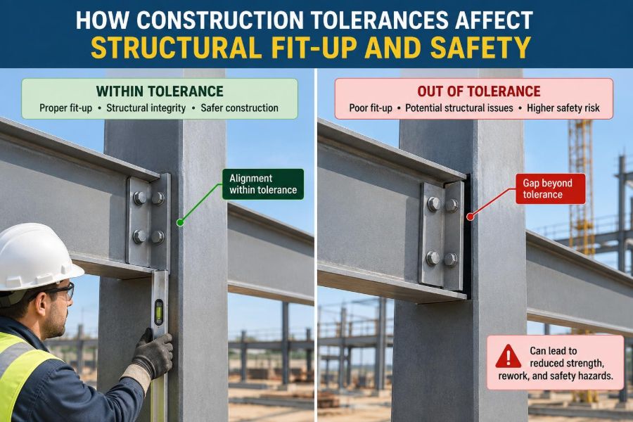

A steel beam arrives on site with bolt holes that appear to be only slightly out of position. A precast wall panel is a little wider than the opening prepared for it. A column base plate sits on grout that is higher at one corner than another. None of these conditions may look dramatic from a distance.
Yet construction is an assembly process. Structural members, connections, finishes, services, and temporary works must occupy compatible positions in three dimensions. A small dimensional difference can become a difficult field problem when several components meet at the same location.
This is where construction tolerances matter. They define how much variation is permitted in manufactured materials and completed work while still allowing the structure to fit together, perform as intended, and be built safely.
For students, tolerances can seem like a drafting detail. For working professionals, they are often the difference between a routine installation and a chain of redesigns, delays, unsafe modifications, or disputes. Understanding them means understanding how a design survives contact with real construction.
📏 1. Tolerance Is Permitted Variation
A tolerance is the allowed departure from a stated dimension, location, level, alignment, or geometry. It recognizes that no field measurement, fabrication process, or installation operation produces perfectly exact results every time.
For example, a drawing may specify a member length, but the applicable specification may permit a defined positive or negative variation. The required dimension is called the nominal dimension; the permitted range around it is the tolerance.
Tolerance is not permission for careless work. It is a controlled limit established so that normal variation does not compromise fit, function, strength, appearance, or safety.
🧩 2. Fit-Up Is the Practical Test
Fit-up describes whether components can be assembled in their intended locations without forcing, damaging, or improperly altering them. Good fit-up allows a connection to be completed with the specified bolts, weld access, clearances, and bearing surfaces.
A component can be within its individual fabrication tolerance and still create a fit-up problem. This happens because the component must fit with adjacent work that also has its own permitted variation.
The field question is therefore not simply, “Is this piece close enough?” It is, “Can all interacting pieces perform their intended roles together?”
🏗️ 3. Structural Work Is an Interface System
Most tolerance problems occur at interfaces: the places where one trade, material, or structural element meets another. A steel frame meeting concrete foundations, precast cladding meeting embeds, or reinforcing steel meeting congested connection hardware are typical examples.
Each party may have completed its work acceptably when viewed alone. The conflict appears only when their work is brought together. That is why interface dimensions deserve more attention than dimensions that affect only one isolated part.
Designers should identify these interfaces early, especially where there is little room for adjustment after fabrication.
📚 4. Design, Fabrication, and Erection Tolerances Differ
Tolerances occur at several stages, and they should not be treated as interchangeable. Design tolerance is the variation the structural concept can accommodate. Fabrication tolerance concerns dimensions produced in a shop or plant. Erection tolerance concerns the final position of work in the field.
A steel fabricator may accurately produce a beam, while erection still places that beam slightly off line. Similarly, a concrete contractor may place anchor rods within the stated construction tolerance, while their final pattern remains difficult for a rigid base plate to accept.
Specifications, approved shop drawings, and relevant project standards must establish which tolerances govern each activity.
📐 5. Location, Size, Plumbness, and Level Are Separate Controls
Not all variation is the same. A member can have the correct size but be in the wrong location, or be correctly located at its base but lean out of plumb.
| Control | What it addresses | Typical fit-up consequence |
|---|---|---|
| Size | Length, width, thickness, diameter | Member is too long, short, thick, or thin for its connection |
| Location | Position relative to grid lines or reference points | Holes, embeds, and supports do not align |
| Level | Vertical elevation | Uneven bearing, poor drainage, or incompatible floor transitions |
| Plumbness and alignment | Verticality, straightness, and line | Frames rack, panels drift, and connections lose adjustment range |
Checking only one dimension can therefore create false confidence. The relevant geometry must be checked in the directions that affect the connection.
➕ 6. Tolerance Stack-Up Explains Small Errors Becoming Big Ones
Tolerance stack-up occurs when allowable variations from several components accumulate. Imagine a foundation, anchor rods, base plate holes, column geometry, beam connection, and adjacent panel all varying in unfavorable directions. The final mismatch can be much larger than any single deviation.
This is not a prediction that every tolerance will occur at its maximum value. It is a design and planning issue: a connection with almost no adjustment may be unreliable if realistic combined variation can consume its available clearance.
Critical interfaces need a tolerance analysis, whether a formal calculation or a disciplined geometric review.
🎯 7. Datum Control Keeps Measurements Meaningful
A datum is a reference from which locations and elevations are established. Grid intersections, benchmark elevations, face-of-column lines, and centerlines can all serve as project datums.
Without clear datums, workers may measure from nearby finished work that is itself slightly displaced. Errors then propagate from one element to the next. This is sometimes called “chasing dimensions” across a project.
Survey control should be established, protected, verified, and communicated. The most reliable layout work returns to primary control rather than relying on a long chain of secondary measurements.
🧱 8. Concrete Creates Early Geometric Constraints
Cast-in-place concrete often sets the geometry for everything above or beside it. Footing locations, wall faces, slab edges, blockouts, sleeves, and embedded plates may later control steel, precast, curtain wall, machinery, and architectural finishes.
Concrete has additional challenges: formwork movement, placement pressure, curing behavior, shrinkage, and difficulty measuring inaccessible embedded items after the pour. Once concrete gains strength, correction can be expensive and disruptive.
This makes pre-pour verification especially valuable. It is usually easier to adjust an anchor-rod template than to repair a completed pedestal.
🔩 9. Anchor Rods Are a High-Consequence Interface
Anchor rods connect structural steel, equipment supports, and other items to concrete. Their locations must suit the actual base plate, not merely a general idea of where the column will stand.
Common problems include incorrect spacing, rotation of the rod group, insufficient projection, damaged threads, and rods that are not adequately vertical. A mismatch may prevent the base plate from seating or leave inadequate room for nuts, washers, and welding operations.
Enlarging holes or heating and bending rods is not a routine field solution. Such changes can alter load transfer and must be evaluated by the responsible design professional using project-specific information.
🏭 10. Steel Fabrication Accuracy Does Not Eliminate Field Variation
Structural steel is commonly fabricated under controlled shop conditions, but transport, handling, assembly sequence, temperature, and erection all influence the installed geometry. Long members can deflect under self-weight, and connection points may move as the frame is stabilized.
Steel connections often contain some adjustment through bolt-hole clearances, shims, slotted holes where specifically designed, or weld fit-up provisions. That adjustment is finite and purposeful; it should not be assumed to solve major layout errors.
Early erection surveys can reveal drift before it reaches upper stories or cladding interfaces.
🪚 11. Wood Construction Has Moisture and Material Variability
Wood products can change dimensions with moisture content, particularly across the grain. Sawn lumber also has natural variability, while engineered wood products have their own manufacturing and installation requirements.
A framing layout that seems acceptable when dry may behave differently after exposure to weather. Crowns, warping, shrinkage, and cumulative stud-height variation can affect bearing, finishes, door openings, and connections.
Good wood fit-up relies on material storage, moisture management, realistic details, and attention to how repeated members accumulate variation over a long wall or floor line.
🏢 12. Precast Concrete Needs Deliberate Adjustability
Precast elements are manufactured before their final field conditions are fully realized. Panel dimensions, embed locations, erection hardware, support steel, and adjacent construction must therefore work as a coordinated system.
Connections frequently include adjustable features because panels must be set to line, level, and plumb while accommodating realistic variation in the supporting structure. The connection must then be completed in its final designed configuration.
A narrow architectural joint can be visually desirable, but it may leave little installation tolerance. The design team must balance appearance, weathering needs, movement, and erection practicality.
🧷 13. Rebar Congestion Can Defeat a Correct Design on Paper
Reinforcing steel is often detailed in a two-dimensional view, while construction occurs in three dimensions. At beam-column joints, transfer regions, heavily loaded walls, and anchorage zones, bars, ties, couplers, studs, and embedded items may compete for the same physical space.
If workers cannot place and consolidate concrete around the reinforcement, the intended strength and durability may not be achieved. Forcing bars aside can also reduce cover, alter spacing, or damage coatings.
Congested details deserve constructability review, enlarged-scale drawings, and where appropriate, coordinated three-dimensional modeling before work reaches the site.
🕳️ 14. Bolt Holes Provide Limited, Not Unlimited, Forgiveness
Bolt holes are designed with defined types and dimensions. Their geometry affects installation and the way forces transfer through a connection. Standard holes, oversized holes, and slotted holes are not interchangeable conveniences.
Using a larger field-drilled hole than detailed can reduce bearing area, change slip behavior, or conflict with the assumptions used in connection design. The correct response to a bolt mismatch is to document the condition and obtain an engineered resolution.
The same principle applies to torch-cutting, welding over holes, or substituting bolts. A workable-looking repair is not automatically a structurally acceptable one.
⚖️ 15. Tolerances Must Respect Load Paths
A load path is the route by which forces travel through a structure to its supports and foundations. Tolerance-related changes can redirect or concentrate those forces.
For instance, a support that bears only at one edge rather than across its intended surface may introduce local bending, crushing, or rotation. An eccentric connection, meaning one shifted away from the intended line of force, can add moment that the original detail did not intend.
Fit-up decisions should therefore be judged by more than whether parts can be connected. They must preserve the intended bearing, alignment, stiffness, and force transfer.
🧰 16. Shims, Grout, and Pack Plates Have Specific Roles
Shims and pack plates can establish elevation or provide firm bearing when they are designed and installed appropriately. Non-shrink grout is commonly used beneath base plates to create uniform support after the steel has been positioned and leveled.
These materials are not generic remedies for every gap. Excessive shim stacks, unsupported plate edges, incomplete grout contact, or improvised filler can produce local stress concentrations and long-term performance problems.
The detail should state the intended sequence: position the member, provide temporary support where needed, tighten or complete the connection as specified, then grout or finish the permanent bearing condition.
🌡️ 17. Temperature Changes Dimensions During Construction
Materials expand and contract as temperature changes. On a long steel frame, a temperature difference between fabrication, morning layout, and afternoon installation can noticeably affect fit-up at distant points.
Temperature is especially relevant for long members, bridge components, rails, facade systems, and assemblies exposed to direct sunlight. It does not excuse poor layout, but it can explain why a dimension checked at one time does not match later conditions exactly.
For sensitive work, teams should use consistent measurement practices, consider material temperature, and follow the project’s survey and erection procedures.
🌬️ 18. Temporary Conditions Can Distort Final Geometry
A structure under construction is not always behaving like the completed structure. A partially erected frame may be flexible, a precast panel may be supported temporarily, and fresh concrete may not yet provide its final restraint.
Wind, construction loads, temporary bracing, and erection sequence can influence measured positions. Releasing a brace or placing an additional level of framing may change alignment.
This is why temporary works and sequence planning matter to tolerance control. A final survey should occur when the relevant permanent load condition and restraint system are sufficiently established.
🧭 19. Surveying Is a Construction Control Process
Surveying is not merely a one-time layout task. It supports verification before construction, monitoring during assembly, and confirmation of completed geometry.
Effective survey practice uses documented control points, suitable instruments, trained personnel, clear acceptance criteria, and records that identify what was measured and when. For critical work, an independent check can catch transcription, setup, or reference errors.
Measurements should be interpreted in context. A single point may be acceptable while the overall line, plane, or connection pattern is not.
📝 20. Shop Drawings Turn Intent into Buildable Geometry
Contract drawings establish design intent, while shop drawings, fabrication drawings, and erection drawings translate that intent into manufacturing and installation information. They are where many tolerance-sensitive dimensions become explicit.
Good submittals identify member marks, connection geometry, hole patterns, embed positions, reference lines, erection assumptions, and any required adjustment. Conflicts should be resolved before fabrication rather than discovered with a crane waiting.
Review does not transfer all coordination responsibility to the reviewer. Each project participant must follow the contractual process and verify work within their scope.
🖥️ 21. Digital Models Help, but They Are Not the Field
Building information modeling can reveal clashes and improve coordination, particularly where structure, reinforcement, mechanical systems, and architectural elements share tight spaces. A model can also help teams visualize erection access and connection adjustment.
However, a model may represent nominal geometry without showing permitted construction variation, survey uncertainty, material movement, or practical installation clearances. A visually clash-free model can still create a difficult field condition.
Use digital coordination as an aid to tolerance planning, not as proof that fit-up is guaranteed. Model tolerances, datums, and responsibility boundaries should be discussed explicitly.
🚧 22. Unsafe Field Fixes Often Begin as Schedule Pressure
When a part does not fit, the job may be under pressure to keep crews productive and equipment moving. That is when unapproved modifications become most tempting: forcing members into place, cutting reinforcement, welding without a procedure, or changing holes in the field.
These actions can create hazards during installation and can reduce capacity, ductility, durability, fire protection, or inspection quality afterward. They may also conceal the original dimensional issue, making later evaluation harder.
Stop, stabilize, document, and escalate is usually the safer sequence. A delay for technical review is preferable to embedding an unverified change in the structure.
📸 23. A Clear Nonconformance Report Speeds Resolution
A dimensional problem should be recorded as a factual condition, not as an assumption about fault. Useful documentation includes marked-up drawings, measured dimensions, survey references, photographs with scale where helpful, component identification, and the work status.
The report should explain the practical effect: for example, “base plate cannot seat over rods” or “required edge distance is not available,” rather than simply saying “does not fit.” This helps the engineer assess consequences quickly.
Do not conceal work, permanently alter components, or proceed beyond safe temporary conditions while awaiting direction unless the responsible parties authorize a specific action.
🔍 24. Inspection Should Focus on Critical Features First
Not every dimension has equal structural consequence. Inspection effort should prioritize features that govern bearing, connection capacity, stability, clear cover, fire-resistance interfaces, drainage slopes, and movement joints.
A practical inspection plan may include hold points before concrete placement, before steel erection advances beyond a level, before grouting, and before inaccessible connections are covered. These checks are most valuable when they occur while correction remains feasible.
Acceptance criteria must come from the project documents and applicable requirements, not from a visual judgment that the work “looks about right.”
🛠️ 25. Designing for Adjustment Is Good Engineering
Robust details recognize that construction has variation. Reasonable adjustment can be provided through connection geometry, shims, leveling nuts, toleranced joint widths, accessible bolts, field-welded closure details, or deliberately sequenced work.
The goal is not to make every connection loose. Excessive flexibility can impair stiffness, weather performance, appearance, or load transfer. The goal is to provide controlled adjustability where it is needed and to specify how the final condition is secured.
Designs that require perfect placement across several independent trades are often fragile, even if they look efficient on paper.
👷 26. Communication Defines Who Acts and When
Tolerance control depends on communication among the owner, design team, general contractor, trade contractors, fabricators, surveyors, inspectors, and field crews. The key questions are straightforward: What is the reference? Which tolerance applies? Who verifies it? What happens if it is exceeded?
Preconstruction meetings and trade coordination sessions are useful places to identify high-risk interfaces. Crews also need installation information that is clear enough to use at the point of work, not only buried in a specification.
Respectful communication matters. Reporting a mismatch early is a professional act that protects the project, rather than an inconvenience to be ignored.
🧠 27. Common Tolerance Mistakes Are Usually Predictable
Many fit-up failures arise from recurring habits rather than mysterious technical events. Recognizing them helps teams prevent trouble before materials arrive.
- Assuming nominal drawing dimensions are exact field dimensions.
- Measuring from unverified secondary references.
- Leaving embed, sleeve, and anchor-rod coordination until immediately before placement.
- Using adjustment intended for minor variation to absorb a major error.
- Approving a field fix based only on appearance or convenience.
- Checking individual parts but not the assembled interface.
The corrective theme is consistent: establish control, review interfaces, verify early, and obtain proper direction for deviations.
✅ 28. A Practical Fit-Up Workflow
A repeatable workflow reduces last-minute surprises. The exact process varies by project, but the following sequence is broadly useful:
- Identify interfaces with limited adjustment or high safety consequences.
- Confirm governing drawings, specifications, datums, and acceptance criteria.
- Review accumulated variation and make required adjustments before fabrication.
- Verify layout, templates, embeds, and supports before irreversible work.
- Inspect incoming components and preserve their identification.
- Survey and check fit-up during erection, before finalizing connections.
- Document deviations promptly and complete only approved corrective work.
This approach turns tolerance management from reactive troubleshooting into planned quality control.
🏁 29. The Core Principle: Buildability Protects Structural Performance
Construction tolerances are not minor administrative limits. They connect design intent to the physical realities of measuring, fabricating, transporting, erecting, and inspecting structural work.
Good fit-up preserves the load path, allows specified connections to function, avoids unsafe improvisation, and gives adjacent systems the room they need. Poor fit-up can increase cost and delay, but its more serious consequence is the possibility of altered structural behavior or hazardous field work.
The strongest approach is to anticipate variation rather than deny it: define reliable datums, coordinate interfaces, provide purposeful adjustment, verify critical geometry, and treat out-of-tolerance work as an engineering decision.
A structure fits safely when its design, fabrication, and installation tolerances are coordinated as one system—not checked as isolated dimensions.
That mindset helps teams solve problems while they are still small, visible, and controllable—and it makes the finished structure more likely to perform as intended. 📐🏗️✅