
A wrench turning a stubborn bolt feels straightforward: your hand applies a force, and the bolt twists. But the same basic action can occur in parts of a structure that never look like a wrench.
A balcony edge beam may twist because the slab frames into only one side of it. A curved ramp may twist under traffic. A building beam supporting an offset façade or a projecting canopy can rotate as loads try to turn it about its length.
That turning action is called torsion. It is often less visually obvious than bending or compression, yet it can control reinforcement, connections, cracking, vibration, and serviceability.
Understanding torsion helps engineers see where a seemingly ordinary load path becomes three-dimensional. It also explains why a member can be strong in bending but still perform poorly when it is asked to resist twisting.
🔄 What Torsion Means in Structural Engineering
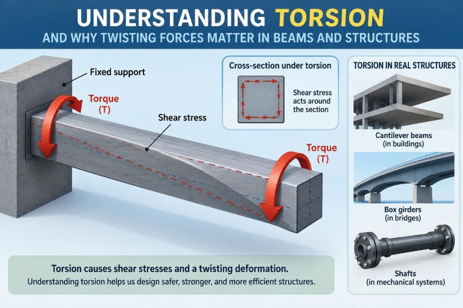
Torsion is the twisting of a structural member caused by a torque, also called a torsional moment. Torque is a moment that acts around the member’s longitudinal axis rather than around a transverse axis.
Imagine holding one end of a ruler fixed and rotating the other end. The ruler is being twisted. In a beam, a torsional moment tries to rotate one cross-section relative to another along the beam’s length.
Engineers commonly denote torque by T. Its units are force multiplied by distance, such as kN·m, just like a bending moment. The units match, but the physical action and the resulting stresses are different.
🧭 Bending, Shear, and Torsion Are Different Actions
A beam rarely experiences only one internal action. Vertical loads commonly produce bending moment and shear force; an eccentric or uneven load path can add torsion.
| Action | What it tries to do | Simple visual example |
|---|---|---|
| Axial force | Stretch or shorten a member | Pulling or pushing a rod |
| Bending moment | Curve a member | Loading the middle of a shelf |
| Shear force | Slide one part past another | Cutting action near a support |
| Torsion | Rotate one end relative to the other | Turning a screwdriver |
A useful distinction is that bending usually creates tension on one side of a section and compression on the other. Torsion produces mainly shear stresses that circulate around the cross-section.
🛞 The Everyday Intuition Behind Torque
Torque depends on both force and lever arm. Pushing a door near its hinges takes more force than pushing at the handle because the handle is farther from the axis of rotation.
The same principle applies to structural loading. When a load acts away from a beam’s shear center or an appropriate support line, it has an eccentricity. Force times eccentricity creates a torsional moment.
A load does not need to look rotational to produce torque. A downward force on one side of a beam can create twisting simply because its line of action is offset.
📐 Where Torsion Appears in Real Structures
Torsion appears wherever geometry, loading, or support conditions prevent loads from passing directly through a member’s preferred load path. Common situations include:
- edge beams supporting slabs from one side only;
- curved bridge girders and curved ramps;
- spandrel beams carrying façade panels or floor loads eccentrically;
- canopies, awnings, and sign supports with offset loads;
- stair landings and stringers with asymmetric support;
- members in irregular building frames, especially around setbacks and transfer levels.
Some torsion is intentional and obvious, as in a drive shaft. In buildings, it is more often a consequence of arranging members and loads in space.
🧱 Why Edge Beams Are Frequent Torsion Members
An interior beam may receive slab load from both sides. If the slab geometry and loading are balanced, the beam is primarily bent downward, with limited net twisting.
An edge beam, by contrast, often supports a slab on only one side. The slab reaction acts at an offset from the beam’s centerline, creating torque in addition to bending and shear.
This does not mean every edge beam is torsion-critical. Slab continuity, adjacent members, diaphragm action, and support restraint can redistribute effects. But the one-sided loading condition should prompt deliberate analysis rather than an assumption that the beam behaves like an interior beam.
🌉 Curved Beams Turn Vertical Load into Twist
Curved members are a classic torsion problem. On a straight, simply supported beam, a vertical load applied along the span can often be carried mainly by bending and shear.
On a curved beam, the reactions and internal forces must follow a changing direction. Vertical loading can therefore generate significant torsion, often coupled with bending and shear. The precise distribution depends on curvature, support details, bracing, and stiffness.
Curved ramps, ring beams, and horizontally curved bridge girders deserve three-dimensional modeling or carefully selected simplified methods. Treating them as straight beams can overlook a governing action.
🧩 Equilibrium: Finding the Source of Twist
The first step in a torsion problem is not selecting reinforcement or calculating a stress. It is drawing a free-body diagram and locating every load relative to the member’s axis and supports.
If a resultant force V acts at perpendicular distance e from the relevant axis, its torque is conceptually:
T = V × e
This expression is simple, but the structural interpretation may not be. The relevant eccentricity can change along a member, and reactions, slabs, diaphragms, or secondary framing may share the torque.
🌀 What Happens Inside a Twisted Member
Under torsion, one cross-section wants to rotate relative to the next. Material within the member resists that relative rotation through shear stress.
For a circular shaft under ideal elastic torsion, the stress distribution is relatively intuitive: shear stress is zero at the center and increases toward the outside. Material near the perimeter contributes strongly because it lies farther from the axis.
Most structural beams are not circular shafts. Their stress patterns are more complicated, particularly for open sections such as I-beams, channels, and angles. Still, the perimeter’s role remains a useful physical intuition.
📏 Angle of Twist and Torsional Stiffness
Strength is not the only question. A member may resist a design torque without failing yet rotate enough to crack finishes, distort cladding supports, create ponding problems, or make a floor feel flexible.
The rotation along a member is described as its angle of twist. In basic elastic behavior, twist increases with torque and member length, and decreases as the material’s shear modulus and the section’s torsional stiffness increase.
For idealized cases, this relationship is often represented by a form involving GJ, where G is shear modulus and J is a torsional section property. The correct meaning of J depends on the section and torsion type; it should not be assumed to be the same as a familiar bending property.
⭕ Circular Sections Behave Differently from Rectangular Ones
Closed circular sections distribute torsional shear efficiently around their perimeter. This is one reason tubes are excellent for shafts, bicycle frames, and many torsion-dominated components.
Solid rectangular sections can resist torsion, but their shear stress distribution is nonuniform. Stresses concentrate near parts of the boundary, and corners do not behave as a simple “maximum-at-the-corner” sketch might suggest.
Section shape matters as much as area. Two members with similar material area can have very different torsional stiffness and torsional strength.
📦 Closed Sections Resist Twist Efficiently
A hollow box beam, rectangular tube, or closed steel box girder creates a continuous path for shear flow around its perimeter. Shear flow is the distributed shear force carried along a thin wall.
When a closed section twists, the walls work together in a circulating pattern. This can provide substantially greater torsional efficiency than an open section with similar material quantity.
That advantage is not automatic. Thin walls can buckle, welded seams must transfer the shear flow, diaphragms may be required, and access openings can interrupt the load path. A closed shape is effective only when its continuity is maintained.
🔓 Open Sections Can Be Torsionally Flexible
I-sections, channels, tee sections, and angles are called open sections because their walls do not form a closed loop. They are often very efficient for bending about a strong axis, but they may have relatively low resistance to ordinary twisting.
Under torsion, an open section can experience large rotation even when bending stresses are modest. A channel loaded away from its shear center may visibly twist as well as deflect.
Adding a plate to close a section, using paired members with adequate diaphragms, or changing the load path can greatly improve performance. Simply choosing a deeper open beam primarily improves bending stiffness; it may not solve a torsion problem.
🧠 Saint-Venant Torsion and Warping Torsion
Introductory calculations often focus on Saint-Venant torsion, the familiar form of torsion in which cross-sections are free to warp as they twist. Warping means that points in a cross-section can move longitudinally by different amounts.
In long open sections, this warping can be substantial. If supports, connections, diaphragms, or adjacent members restrain it, the member develops additional longitudinal stresses. This is called warping torsion.
The distinction matters especially in steel I-girders, box girders, and members with rigid end restraints. A model that captures only simple torsion can miss stresses created by restrained warping.
🧷 The Shear Center Explains Unexpected Twisting
The shear center is the point in a cross-section through which transverse load must act to avoid twisting caused by shear. It is not necessarily the centroid.
For doubly symmetric sections, such as a conventional symmetrical I-section, the shear center typically coincides with the centroid. For channels, angles, and other unsymmetrical open sections, it may lie outside the material itself.
This is why hanging a load through what appears to be the “middle” of a channel can still make it twist. The force misses the shear center, creating torque.
🏢 Global Building Torsion Is Not Beam Torsion
The word torsion is also used at the building scale. A building can twist as a whole under wind or earthquake loading when the center of mass and the center of lateral stiffness are offset.
For example, an irregular arrangement of shear walls may be much stiffer on one side of a plan than the other. Lateral force can then cause translation plus rotation of the floor diaphragm.
This global torsion differs from the local twisting of an individual beam, but the underlying idea is related: an eccentric force path produces rotation. Good design considers both scales and how global movement affects individual elements.
🧮 Load Paths Decide Whether Torsion Is Primary
Not every calculated torsional moment requires the same level of member capacity. Engineers distinguish between torsion that is essential to equilibrium and torsion that can reduce after cracking or redistribution.
Equilibrium torsion is required to maintain a stable load path. A perimeter beam supporting a slab edge with no alternate route may need to carry the torsion directly. Removing its torsional resistance could compromise the load path.
Compatibility torsion can arise because connected members must deform together. In some redundant systems, cracking or yielding may allow moments to redistribute, subject to code provisions and serviceability needs. The distinction is structural, not a license to ignore torsion.
🏗️ Reinforced Concrete Changes After Cracking
Concrete has limited tensile capacity. Once torsional tensile stresses cause cracking, a reinforced concrete member no longer behaves like an uncracked solid block.
Cracks associated with torsion often form diagonal, helical-looking patterns around the beam. Reinforcement must bridge these cracks and provide a coherent force path together with the concrete compression field.
Design approaches for reinforced concrete torsion commonly use a thin-walled tube analogy after cracking. Closed stirrups and longitudinal bars work together: the stirrups resist transverse components, while the longitudinal steel carries corresponding forces along the beam.
🪢 Why Closed Stirrups Matter in Concrete Beams
Open U-shaped stirrups may be useful for certain shear arrangements, but torsion requires a closed transverse reinforcement path to encircle the core effectively. The reinforcement must be detailed so forces can develop around the section.
Longitudinal torsion bars are also needed, often placed near corners where they can participate in the torsional truss mechanism. Bar placement, anchorage, lap locations, cover, and stirrup hooks are not drafting details; they determine whether the intended mechanism can form.
Combined shear and torsion must be checked together. Designing shear reinforcement for shear alone and then adding a separate torsion quantity without considering interaction can produce an incomplete design.
🔩 Steel Members Need More Than a Strong Section
Steel can remain elastic over a useful range, but torsion still brings design concerns beyond nominal strength. Thin plates may buckle in shear, welds may be heavily loaded, and connections can introduce local distortion.
In a steel box girder, internal diaphragms help preserve cross-sectional shape and distribute concentrated loads. In open girders, lateral bracing and warping restraint can materially affect torsional response.
Connection geometry is critical. A torsional moment must enter and leave a member through real forces in bolts, welds, plates, and adjoining members. A model may show torque at a node, but the detail must establish a physical couple to transfer it.
🪵 Timber and Composite Members Have Their Own Limits
Timber is anisotropic: its properties vary with grain direction. Torsion can be especially sensitive to knots, splits, checks, moisture conditions, and connection layout. Designers should use material-specific design provisions rather than applying steel or concrete intuition directly.
Composite members add another question: can the components transfer shear well enough to act together under torsion? A steel beam with a concrete slab may gain restraint in some configurations, but that restraint depends on connectors, cracking, slab geometry, and boundary conditions.
Assumed composite torsional behavior should be justified. It is unsafe to count on a slab, deck, or cladding panel merely because it is physically nearby.
📊 Combining Torsion with Other Internal Forces
Real members often carry axial load, bending about one or two axes, shear, and torsion simultaneously. These effects can interact through stresses, yielding, cracking, buckling, and deformation compatibility.
A beam under strong bending may already have a compressed flange close to local buckling limits. Added torsion can increase demand on web panels, connections, or bracing. Similarly, concrete torsional cracking can alter shear capacity and stiffness.
Design standards provide interaction methods appropriate to a material and limit state. The engineer’s task is first to identify the relevant combined actions accurately; no interaction equation can repair an unrealistic load model.
🧱 Torsion Can Trigger Serviceability Problems
Serviceability concerns arise before ultimate strength is reached. Excessive twist can crack brittle finishes, misalign doors, distress glazing, rotate bearing surfaces, or make drainage slopes ineffective.
For a hypothetical projecting canopy, a small rotation at the support may become a noticeable vertical movement at its outer edge. The canopy might remain safe by strength calculations while still causing façade joint problems or water collection.
Where appearance, alignment, vibration, or waterproofing matter, designers should assess torsional stiffness as well as resistance. Construction tolerances and connection slip can also contribute to observed rotation.
⚠️ Torsional Buckling and Stability Risks
Compression members can fail through flexural-torsional buckling, a coupled mode involving bending and twist. Slender, open, or unsymmetrical sections are particularly sensitive because their torsional stiffness may be limited.
Beams can also undergo lateral-torsional buckling: the compression flange moves laterally while the member twists. This is not identical to applied torsion, but torsional stiffness and restraint are central to the behavior.
Bracing locations, load application points, unbraced lengths, and connection restraint all affect stability. A member that looks adequate in a two-dimensional bending check may be vulnerable in its actual three-dimensional configuration.
🧪 A Simple Conceptual Example
Consider a rectangular concrete edge beam supporting a one-way slab on its inner side. The slab reaction is vertical, but its resultant acts some distance from the beam’s centerline.
That offset creates torque. The beam must therefore be examined for vertical bending, shear, and torsion. Near supports, the connection and supporting column or wall must also be able to receive the resulting forces.
If an adjacent return beam, slab diaphragm, or wall offers an alternative route, the actual torque may differ from a simple isolated-beam estimate. The example illustrates why structural context is as important as the equation T = V × e.
🖥️ Modeling Torsion Without Fooling Yourself
Structural analysis software can report torsional moments with impressive precision. That does not guarantee that the result represents physical behavior. Torsion is sensitive to stiffness assumptions, releases, offsets, diaphragm definitions, mesh density, and boundary conditions.
A member modeled as perfectly fixed against rotation may attract much more torsion than a flexible real connection can transmit. Conversely, an unintended moment release can eliminate torsion that a welded or monolithic detail would actually develop.
Useful checks include hand-calculated equilibrium, deformed-shape review, reaction checks, and comparison of alternate reasonable stiffness assumptions. Model output should support engineering judgment, not replace it.
🔍 Reading Cracks and Deformations in Existing Structures
Diagonal cracks that wrap around a concrete member, unusual rotation at supports, or repeated distress at cladding connections can suggest torsional behavior. They are clues, not proof of a single cause.
Assessment should consider load history, changes in use, corrosion, settlement, thermal movement, construction sequence, and nearby alterations. A crack pattern can reflect combined shear, bending, restraint, or local connection forces.
When torsion is suspected in an existing structure, an appropriately qualified engineer should evaluate the complete system. Repairs that merely seal cracks without restoring or reducing the underlying force path may not address the problem.
🛠️ Design Strategies for Reducing Torsion
The most efficient torsion solution is often geometric: prevent unnecessary eccentricity before increasing member size or reinforcement.
- Align loads and supports where practical so force paths pass near the intended resisting axis.
- Use symmetric framing when architectural requirements allow it.
- Select closed or box-like sections for members that must resist substantial twist.
- Add diaphragms, cross-frames, or bracing to stabilize shape and distribute loads.
- Provide intentional torsional connections rather than relying on incidental restraint.
- Detail reinforcement, welds, bolts, and anchors for the complete torsional force path.
These strategies involve trade-offs. A box section may improve torsion but complicate fabrication, inspection, drainage, or corrosion protection. The right choice depends on the full project context.
🚫 Common Mistakes When Checking Torsion
One common error is assuming that a member with adequate bending capacity automatically has adequate torsional capacity. Bending strength, shear strength, and torsional stiffness are related only indirectly.
Another is treating every software torsion value as equilibrium torsion. Some values result from compatibility in a highly redundant model and may require interpretation under the applicable design standard.
Other avoidable mistakes include:
- ignoring the shear center of an open steel section;
- using open stirrups where closed torsional reinforcement is required;
- forgetting that torsion must be transferred through supports and connections;
- neglecting warping restraint in long open sections;
- checking strength while overlooking rotation, cracking, or stability.
📋 A Practical Workflow for Torsion Problems
A disciplined sequence makes torsion easier to manage. Start with geometry and load paths before turning to detailed equations.
- Identify members with eccentric loads, curved geometry, asymmetric framing, or restrained open sections.
- Draw free-body diagrams and locate the lines of action of loads and reactions.
- Decide whether torsion is required for equilibrium or arises through compatibility.
- Select an analysis method appropriate to the structure’s material, geometry, and redundancy.
- Check strength, deformation, stability, and connections under combined actions.
- Detail a continuous path for the torsional forces to enter, travel through, and leave the system.
- Review constructability, inspection needs, and how field conditions may alter restraint.
This workflow does not replace code-based design, but it prevents many conceptual omissions before calculations become elaborate.
🎓 Core Takeaway: Torsion Is a Load-Path Problem
Torsion is not merely a specialized formula for twisted bars. It is the structural consequence of forces acting with eccentricity, sections resisting rotation, and connections determining whether that resistance can develop.
Closed sections generally resist ordinary torsion efficiently, while open sections may twist or warp significantly. Reinforced concrete relies on carefully detailed closed stirrups and longitudinal steel after cracking; steel and other materials require equally deliberate attention to stability, plate behavior, and connections.
The core habit is simple: whenever a load is offset, a beam is curved, or a section is unsymmetrical, ask where the turning moment goes. Good torsional design makes the complete three-dimensional load path visible—from load application to final support.
Twisting forces matter because structures do not carry loads only downward; they also carry them through space, around corners, and through connections. Seeing that path clearly is the beginning of sound torsional design. 🏗️🔄📐