
A tenant notices a diagonal crack above a window. A facilities manager sees a floor that seems to dip near a column line. On a bridge inspection, two expansion-joint edges no longer appear level. The first question is usually simple: is it getting worse?
Concrete structures move for many reasons. Some movement is expected from loading, temperature change, shrinkage, creep, and seasonal moisture variation. Other movement can signal distress, loss of support, corrosion, or an unsafe change in how a structure carries load.
The visible symptom is only the starting point. A crack is not a diagnosis, and a single measurement is rarely enough to establish whether a condition is active, stable, or significant.
Good measurement turns an observation into evidence. This guide explains how engineers measure deflection, crack width, and structural movement, how to plan monitoring, and how to avoid drawing conclusions that the data cannot support.
🧭 Start With the Question You Need to Answer
Before choosing an instrument, define the decision that the measurement must support. Is the concern serviceability, such as a bouncy floor or sticking doors? Is it durability, such as a crack that could admit water and chlorides? Or is there a concern about structural safety?
A useful monitoring question is specific: “Does this beam’s midspan displacement increase under similar loading?” is better than “Is the beam moving?” The first question defines a location, direction, comparison condition, and purpose.
📏 Three Measurements That Are Often Confused
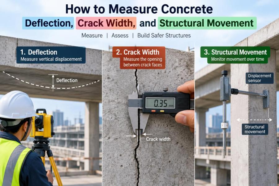
Deflection is the displacement of a member, commonly vertical movement of a beam or slab relative to a reference. Crack width is the separation across the faces of a crack. Structural movement is broader: it can include settlement, rotation, lateral drift, joint opening, or relative displacement between two elements.
A slab can deflect without producing a new visible crack. A crack can widen because of temperature cycling while the overall structure remains stable. Measuring the right quantity prevents misleading conclusions.
🏢 Why Concrete Moves Even When Nothing Is “Wrong”
Concrete is not dimensionally fixed. It shortens as moisture leaves the material, expands and contracts with temperature, and develops time-dependent strain under sustained stress. Reinforcement restrains some of these strains, which can create cracking.
Buildings also respond to use. Occupants, storage, equipment, wind, traffic, and water loads change forces and displacements. The engineering task is to distinguish anticipated behavior from movement that exceeds the structure’s intended performance or changes unexpectedly.
⚖️ Serviceability Is Different From Strength
A member may have adequate strength and still perform poorly in service. Excessive deflection can crack finishes, pond water on a roof, affect partitions, impair drainage, or create uncomfortable vibrations.
Conversely, a fine surface crack does not automatically mean that a member is close to failure. Crack assessment depends on location, pattern, depth, exposure, loading, reinforcement arrangement, and whether the crack is changing.
🔍 Begin With a Condition Survey
Measurement works best after a disciplined visual survey. Record crack locations, lengths, orientations, nearby joints, staining, spalls, rust marks, exposed reinforcement, and any evidence of impact, leakage, or altered loading.
Take overview photographs first, then close-up images with an identification label and scale. A simple drawing or grid helps later inspectors locate the exact crack rather than measuring a similar nearby feature.
🗺️ Establish a Coordinate System and Datum
Every displacement value needs a reference. A datum is a point, line, or surface assumed as the comparison baseline. For settlement monitoring, it may be an external benchmark believed to be stable. For a beam test, it may be a stiff independent reference frame.
Do not use a reference that moves with the element being measured. A ruler held on a flexible floor, for example, cannot reliably show whether the floor itself has moved.
📝 Record Baseline Conditions Before Monitoring
The first reading is a baseline, not a verdict. Alongside each measurement, record date, time, weather where relevant, temperature, occupancy or loading condition, instrument identification, observer, and exact measurement location.
These details explain apparent changes. A joint opening measured in the early morning may differ from an afternoon reading simply because the surrounding material has warmed.
📐 Measuring Deflection With a Straightedge
A straightedge and feeler gauges offer a quick screening method for local surface irregularity. Place the straightedge across a suspected depression and measure the maximum gap beneath it.
This method does not measure the full structural deflection of a beam or slab unless the straightedge spans between meaningful support references. It is most useful for documenting localized curling, unevenness, or surface distortion.
🎯 Dial Gauges for Precise Short-Range Movement
A dial gauge or digital indicator measures small displacement through a contact tip. It is commonly used during load tests, crack movement studies, or laboratory-style investigations where a rigid frame can be installed.
The frame must be independent of the test member. If the gauge stand rests on a slab while measuring that same slab, both may move together and hide the true displacement.
📡 LVDTs and Displacement Transducers
A linear variable differential transformer, usually called an LVDT, is an electronic sensor that converts linear movement into an electrical signal. It is valuable where continuous data collection or high-resolution readings are needed.
Transducers can capture loading and unloading behavior that manual readings miss. Their value depends on careful alignment, secure mounting, calibration, cable protection, and a data logger configured with the correct units and sampling interval.
📷 Surveying Deflection With Levels and Total Stations
Optical levels, digital levels, and total stations measure elevations and coordinates at selected points. They are practical for larger slabs, roofs, façades, retaining walls, and sites where contact gauges are impractical.
Repeatability depends on stable control points, sight distances, instrument setup, and consistent target locations. Survey methods usually reveal broader movement patterns better than they reveal tiny short-term changes.
🛰️ When Laser Scanning and Photogrammetry Help
Laser scanning and close-range photogrammetry can create dense three-dimensional records of a structure. They are especially useful for irregular surfaces, large façades, tunnels, heritage structures, and comparisons of shape over time.
These methods require sound survey control and careful registration between datasets. A colorful point-cloud comparison can look persuasive while actually reflecting alignment error rather than real movement.
📌 Choosing Deflection Measurement Points
For a simply supported beam, maximum vertical deflection often occurs near midspan, so that location is usually critical. For cantilevers, the free end is typically informative. Continuous members and slabs need points selected from the actual support and loading arrangement.
Measure at supports too when possible. What appears to be member deflection may instead be support settlement or rotation. A line of readings across a slab often tells a more useful story than one isolated point.
📉 Separate Total Movement From Residual Movement
During a controlled load test, record readings before loading, during each load increment, at the peak load, after unloading, and after any specified recovery period. The movement under load is not the only result.
Residual movement is the displacement remaining after unloading. Some residual displacement can occur in real materials and systems, but unusually large or increasing residual response deserves engineering review in the context of the test plan and structure.
🔬 Measuring Crack Width With a Crack Comparator
A crack comparator is a transparent card marked with known line widths. Place it directly over a clean crack and compare the visible opening with the printed scale. It is fast, inexpensive, and suitable for routine inspection records.
Its limitations are clear: viewing angle, lighting, surface texture, and operator judgment affect the result. Record the estimated width, the location, and whether it was measured at the widest visible point or at a fixed marked station.
🔎 Crack Microscopes and Digital Measurement
A crack microscope provides magnification and a graduated scale, allowing more repeatable measurements of narrow visible cracks. Some digital microscopes store images, which can improve traceability if the image location and scale are clearly documented.
Magnification does not solve a basic problem: concrete crack faces are rough. The “width” can vary over a few millimeters, so repeat measurements should use the same transverse line across the crack.
🩹 Crack Gauges Show Whether a Crack Is Active
Mechanical crack gauges bridge a crack with two overlapping plates. Their grids show relative opening, closing, and sometimes shear movement. They are useful for observing whether a crack responds to daily or seasonal cycles.
For longer-term monitoring, vibrating-wire gauges, displacement sensors, or other electronic systems may be appropriate. Select a gauge range that accommodates expected motion; a sensor at the end of its range cannot provide reliable trend data.
↔️ Measure More Than Crack Opening
Cracks can move in three basic ways: opening perpendicular to the crack, sliding parallel to it, and displacement out of the surface plane. A diagonal crack in a wall may have both opening and shear components.
A simple width measurement may therefore be incomplete. Where the mechanism is uncertain, install targets or gauges arranged to identify the direction of relative movement, not just the gap visible from one viewpoint.
🧱 Read Crack Patterns Before Judging Width
Pattern often gives more diagnostic information than width alone. Map cracks across the element and look for repeated orientation, concentration near openings, correspondence with reinforcement, or continuity through multiple components.
For example, a distributed network of fine cracks may be associated with restrained shrinkage or surface effects, while a crack concentrated near a support may call for examination of restraint, shear, settlement, or local loading. These are investigation leads, not automatic diagnoses.
🌡️ Temperature, Moisture, and Seasonal Cycles
Concrete and steel respond to temperature, and many joints are designed specifically to accommodate thermal movement. Moisture-related shrinkage and swelling can also alter measured openings and elevations over longer periods.
Take readings at comparable times and conditions when possible. If that is not possible, measure temperature and use a schedule dense enough to reveal cyclic behavior instead of mistaking it for progressive damage.
🏗️ Creep and Shrinkage in Sustained Service
Creep is gradual increase in strain under sustained load. Shrinkage is time-dependent volume reduction, largely associated with moisture loss. Both can contribute to long-term deflection and cracking in reinforced concrete members.
Older structures may still show seasonal change, while new concrete may experience more pronounced early-age changes. Interpreting either condition requires construction history, loading history, member geometry, restraint, and environmental exposure.
🏚️ Settlement, Rotation, and Differential Movement
Settlement is downward movement of a support or foundation. Differential settlement occurs when supports move by different amounts, causing distortion in the supported structure. Rotation is angular change, often observed as sloping floors, tilted walls, or changing joint geometry.
Measure elevations at multiple points tied to stable external control. A single low point does not establish settlement unless the reference and measurement method are credible.
🚪 Practical Clues in Nonstructural Components
Doors that bind, misaligned window frames, cracked finishes, and separated skirting boards can reveal movement, but they are indirect indicators. Wood moisture changes, poor installation, and building fit-out details can produce similar symptoms.
Use these observations to guide inspection locations, not as a substitute for measurement. The structural frame, cladding, partitions, and finishes may all move differently.
🧪 Plan Monitoring Frequency Around the Mechanism
Monitoring frequency should match the expected rate and cause of movement. A suspected immediate change after excavation, impact, or load alteration may require frequent readings. Seasonal joint movement may need readings over months.
| Situation | Useful monitoring approach | Key comparison |
|---|---|---|
| Controlled load test | Readings at each load and unload stage | Load versus deflection and recovery |
| Suspected active crack | Fixed crack gauge with scheduled readings | Trend and temperature response |
| Settlement concern | Repeated level survey from stable control | Relative elevation over time |
| Seasonal joint movement | Readings across different temperatures | Opening versus temperature |
More data is not automatically better. A poorly controlled daily reading can be less useful than a carefully repeatable weekly reading with reliable environmental notes.
✅ Make Readings Repeatable
Mark each station permanently where appropriate, identify the measurement direction, and write a short procedure that another person can follow. Include instrument setup, reference point, gauge orientation, reading resolution, and photo requirements.
Repeatability is especially important when monitoring changes are small. The target is not merely a precise-looking number; it is a measurement whose change is larger than the likely combined field error.
📊 Understand Accuracy, Precision, and Resolution
Resolution is the smallest displayed increment. Precision is how consistently repeated measurements agree. Accuracy is closeness to the true value. A digital display with many decimal places may have fine resolution but poor field accuracy.
Account for instrument tolerance, setup variation, operator technique, temperature effects, and movement of the reference. When readings vary within this uncertainty band, avoid claiming that a meaningful structural change has occurred.
📚 Keep a Defensible Monitoring Log
A clear log makes the data useful to someone who was not present. Include the structure and element ID, station ID, date and time, reading, units, instrument, reference datum, conditions, observer, and unusual events such as rain, construction activity, or changed loading.
Graphs should retain the raw data behind them. Plotting crack width or elevation against time, and sometimes temperature or load, is often more revealing than a long table of isolated values.
⚠️ Common Measurement Mistakes
- Measuring a different point each visit because the location was not marked.
- Using a moving surface as the reference frame.
- Comparing readings taken under very different load or temperature conditions without noting them.
- Reporting crack width without recording crack orientation, location, or measurement method.
- Assuming a visible crack is full-depth or structural without investigation.
- Relying on one reading to declare a condition stable or unsafe.
- Ignoring changes made nearby, such as excavation, added equipment, drainage failure, or removal of a wall.
🚧 Know When to Escalate Immediately
Some observations call for prompt assessment by a qualified structural engineer rather than routine monitoring. Examples include sudden displacement, rapidly changing cracks, significant spalling, exposed or corroding reinforcement, audible distress, loss of bearing, impact damage, or deformation following fire, flooding, excavation, or unauthorized alteration.
Restrict access where there is a credible risk from falling concrete or instability. Monitoring is not a substitute for immediate safety action when conditions suggest acute danger.
👷 Use Codes and Project Criteria Correctly
Acceptable deflection and crack-control criteria depend on the governing design standard, structural system, span, finishes, exposure, loading, and intended use. A limit appropriate for one floor or roof may not suit another.
Inspection measurements should therefore be compared with project-specific documents and engineering judgment, not with a single generic number taken out of context. Existing structures may also require assessment methods different from new-design checks.
🧰 A Practical Field Workflow
- Make the area safe and document the visible condition.
- Define the concern and the movement quantity to measure.
- Select stable datums and permanently identify stations.
- Choose an instrument with suitable range and realistic field precision.
- Take baseline readings with environmental and loading notes.
- Repeat readings to a schedule based on the suspected mechanism.
- Graph trends, review anomalies, and escalate when the behavior changes.
This workflow is deliberately simple. Its strength comes from consistency: the same location, reference, method, conditions, and documentation at each visit.
🧠 The Core Principle: Measure Change in Context
Concrete deflection, crack width, and structural movement are meaningful only when tied to a sound reference and an understanding of the structure’s behavior. A number without a location, direction, baseline, and time history is often just an observation with false confidence.
The most useful investigation combines visual evidence, repeatable measurement, loading and environmental context, and competent engineering interpretation. That combination identifies whether movement is expected, stable, progressive, or in need of urgent action.
Measure the right movement, from a stable reference, repeatedly and in context—then let the trend, not a single symptom, guide the engineering decision. 📏🏗️🔎