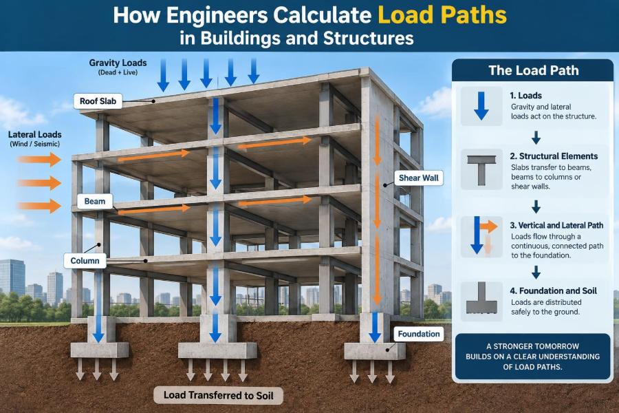

A new floor is added to an office building. The architectural drawings show open-plan space, tall glazing, and a rooftop terrace—but one practical question governs every decision: where do the loads go?
When people stand on a floor, wind pushes on a façade, snow settles on a roof, or an earthquake shakes a frame, the structure must transfer those effects safely into the ground. That continuous transfer is called a load path.
A building rarely fails because one engineer forgot that gravity exists. Problems arise when a connection, member, wall, diaphragm, or foundation interrupts the intended route of force—or when the route was never clearly established in the first place.
Learning to trace load paths helps students understand structural behavior and helps practicing engineers coordinate safer, more buildable designs. It turns a collection of beams, slabs, columns, and walls into a working structural system. 🏗️
🧭 1. Start with the meaning of a load path
A load path is the sequence of structural elements through which a load travels from its point of application to the supporting ground. It is not a physical line drawn through a building; it is a model of how forces are transferred.
For a simple roof, the path may be roof deck to joists, joists to beams, beams to columns, columns to footings, and footings to soil. Real buildings have many overlapping paths, especially where lateral loading is important.
⚖️ 2. Think in forces, not in “weight” alone
Engineers use the word load broadly. It includes gravity effects, but it also includes horizontal forces, deformation effects, pressure, restraint forces, and dynamic actions.
- Dead load: permanent self-weight of structural and fixed building components.
- Live load: movable occupancy, storage, and use-related loading.
- Environmental load: wind, snow, rain, temperature, flood, and seismic effects.
- Construction load: temporary forces during erection, shoring, or sequencing.
A sound load path must be considered for each relevant action, not only for the vertical service condition.
📐 3. Define the structural system before calculating
Before assigning numbers, identify the building’s primary structural system. Is it a steel braced frame, reinforced-concrete flat plate, timber shear-wall building, masonry bearing-wall structure, or a hybrid system?
This decision determines which elements are expected to collect, transfer, and resist load. For example, a concrete slab may support gravity loads directly to columns, while a steel deck commonly delivers load first to secondary beams or joists.
🗺️ 4. Draw a load-path sketch early
A quick hand sketch is one of the best analysis tools available. Mark applied loads, supporting elements, likely reactions, and the final foundation support.
Use arrows to show direction and label member types. If an arrow has no next element to receive its force, the load path is incomplete and deserves immediate attention.
roof load
   ↓
roof deck → joist → girder → column
                           ↓
                        footing → soil
The sketch does not replace analysis software. It tells the engineer what the software model must represent.
🏠 5. Trace the gravity load path from the top down
Gravity analysis often begins at the highest loaded surface. Roof finishes, equipment, snow, maintenance loads, and the roof’s self-weight are carried by the roof assembly.
From there, load moves through framing or bearing elements at each level. A typical vertical sequence is surface, deck or slab, secondary framing, primary framing, vertical supports, foundations, and supporting soil or rock.
Each transfer requires adequate strength, stiffness, bearing area, and connection capacity. 🔽
🧱 6. Understand tributary area
Tributary area is the portion of a loaded surface assigned to a particular supporting member. It is a practical way to convert an area load into a line load, point load, or column reaction.
For regularly spaced beams supporting a one-way slab, an interior beam usually receives load from half the spacing on one side plus half the spacing on the other. Edge beams receive a smaller tributary width unless another element delivers additional load to them.
The method reflects equilibrium, but it should match the actual structural behavior. Irregular geometry, two-way action, discontinuities, and significant stiffness differences can require more refined analysis.
📏 7. Convert area loads into member loads
Floor and roof loads are frequently expressed per unit area. A beam, however, needs a line load; a column typically needs a concentrated reaction.
The basic conversion for a uniformly loaded tributary strip is:
line load on beam = area load × tributary width
Then the beam reactions are determined from its span, supports, and loading pattern. Those reactions become loads on girders, walls, or columns below.
🌉 8. Follow reactions at every support
A support reaction is not the end of the calculation. It is the beginning of the next load-transfer step.
When a beam reaction lands on a girder, the girder must resist that force and pass its own reactions to columns or walls. When a column meets a footing, the footing spreads the column force into the soil.
This repeated process is why engineers often work from small members toward larger collecting members, then downward through the structure.
🪵 9. Check the direction of spanning
Slabs, decks, and panels do not distribute load equally in every direction by default. Their support arrangement, aspect ratio, reinforcement, ribs, and stiffness determine how they span.
A one-way system carries most load across the short distance between parallel supports. A two-way slab can distribute load toward supports in both directions, which changes the demands on beams, columns, and edges.
Assuming the wrong spanning direction can create a convincing-looking but fundamentally incorrect load path.
🧩 10. Separate primary and secondary framing
Secondary members usually support floor or roof surfaces and frame into larger primary members. Joists framing into girders and purlins framing into rafters are familiar examples.
This hierarchy is useful because it organizes calculations. Engineers determine loading on secondary members first, convert their reactions into point or line loads on primary members, and continue toward vertical supports.
Not every frame is perfectly hierarchical, particularly in transfer structures or grids. Still, identifying the hierarchy reveals the intended flow of force.
🔗 11. Treat connections as part of the structure
A beam may have enough bending strength, yet the overall load path can fail if its end connection cannot transfer shear, axial force, or moment. Connections are not accessories; they are force-transfer devices.
Engineers check bolts, welds, reinforcement development, bearing, anchors, embed plates, fasteners, and local supporting material. The connection’s stiffness can also influence how force distributes among parallel paths.
- Can the force enter the connection?
- Can the connection transfer it in the required direction?
- Can the receiving element spread or resist it?
🏢 12. Identify discontinuities and transfer levels
A transfer structure changes the location or arrangement of supports. It may be needed where upper columns do not align with lower columns, such as above a lobby, parking level, or large open room.
Transfer girders, deep beams, trusses, slabs, walls, and podium levels can perform this work. They often carry concentrated, high-consequence loads and may control deflection, cracking, vibration, construction sequencing, or foundation reactions.
Whenever a vertical line of support stops, ask exactly how its force is redirected.
🌬️ 13. Build a separate path for wind loads
Wind acts on exterior surfaces and creates pressure and suction. Those effects must travel from cladding and roof components into the main force-resisting system and then into the foundation.
A simplified path may be façade panel to anchors, anchors to supporting framing, framing to floor diaphragm, diaphragm to braced frame or shear wall, and wall or frame to foundation. Roof uplift follows a similarly continuous path, often ending in hold-downs and foundation anchorage.
Wind is a system-wide connection problem as much as it is a member-design problem. 🌬️
🌎 14. Recognize how seismic load paths differ
Earthquake actions arise from inertia. As the ground moves, the mass of floors, roofs, equipment, and walls resists that acceleration, generating lateral forces within the building.
Floors and roofs collect these forces through diaphragms and distribute them to vertical lateral-force-resisting elements. Those elements transfer forces to foundations, while the foundation system interacts with the moving ground.
Seismic design also requires attention to deformation compatibility, ductility, collector forces, anchorage, and the possibility that elements yield in a deliberate sequence.
🧱 15. Know the job of diaphragms
A diaphragm is commonly a floor or roof system that acts in its own plane to collect and distribute lateral loads. Concrete slabs, metal deck assemblies, timber sheathing, and specially detailed roof systems can serve this role.
Diaphragms deliver force to shear walls, braced frames, or moment frames. They can also transfer forces around openings, re-entrant corners, offsets, and changes in stiffness.
A floor slab may be strong enough for gravity loading but still require careful diaphragm design for lateral action.
🪢 16. Use collectors and chords where forces concentrate
Collectors, sometimes called drag struts, gather diaphragm force and deliver it to a wall or frame. Chords resist tension and compression generated along diaphragm boundaries, much like the flanges of a beam.
These elements become critical where a lateral-resisting wall is not directly under the loaded diaphragm region. A collector bridges the gap between where lateral force is generated and where the resisting element begins.
They must be continuous enough to develop the required force through their connections.
🛡️ 17. Select the lateral-force-resisting system
Most buildings rely on one or a combination of three familiar systems: shear walls, braced frames, and moment-resisting frames. Each has a distinct load path and deformation pattern.
| System | Primary lateral behavior | Typical load-path consideration |
|---|---|---|
| Shear wall | Wall panel resists in-plane shear, bending, and overturning | Diaphragm-to-wall connection and wall anchorage |
| Braced frame | Diagonal members develop axial tension and compression | Brace connections and collector alignment |
| Moment frame | Beam-column joints resist bending and frame sway | Joint continuity and frame deformation |
The best system is not simply the strongest one. It must fit the architecture, foundation arrangement, construction method, and expected deformation demands.
🔄 18. Account for load combinations
Structures are checked under combinations of loads because maximum demand does not usually occur when every load reaches its maximum value at the same time. Design procedures combine relevant actions according to the governing design basis.
Different combinations may control different members. Gravity framing may be governed by one condition, uplift connections by another, and a lateral collector by a wind or seismic condition.
Load paths should be traced for each meaningful combination, especially when load reversal is possible.
↔️ 19. Consider force direction and reversal
Wind can act from opposite directions, and seismic loading can reverse as the building vibrates. A brace that works in tension in one direction may need a companion, a different configuration, or a connection capable of responding to reversal.
Uplift can reverse the usual gravity force at roof connections. A bearing detail that works well under downward compression may not provide the required resistance when tension develops.
Always ask whether the connection and support condition work in both required directions.
📉 20. Check strength, stiffness, and stability together
A complete load path must do more than carry force without breaking. It must also control movement and remain stable as loads act.
- Strength: resistance to required internal forces.
- Stiffness: control of deflection, drift, vibration, and relative movement.
- Stability: resistance to buckling, overturning, sliding, and second-order effects.
A slender column may have adequate material strength but insufficient buckling resistance. A flexible transfer beam may be safe in strength yet cause finishes, partitions, or glazing to perform poorly.
🧮 21. Use equilibrium as a constant check
Every load-path calculation should satisfy equilibrium. The sum of vertical reactions should balance the applied vertical load, and the sum of lateral reactions should balance the applied lateral force, subject to the chosen analysis model.
At local joints, forces and moments must also balance. If reactions grow or disappear unexpectedly between levels, investigate whether a load was counted twice, omitted, or directed to the wrong support.
Equilibrium does not prove that a model is realistic, but failure to satisfy it proves that something is wrong.
💻 22. Model the intended behavior, not just the geometry
Analysis software can rapidly calculate reactions and internal forces, but it only analyzes the supports, releases, stiffnesses, and connectivity that the engineer defines. A visually complete model can still contain disconnected or unintended load paths.
Review member end releases, diaphragm assignments, offsets, panel zones, boundary conditions, meshing, and load directions. Compare selected results with hand calculations and simple free-body diagrams.
The question is not “Did the model run?” It is “Does the model reflect a buildable force-transfer mechanism?”
🔍 23. Inspect local effects at load introduction points
Forces often enter a member over a small area. This can create local bending, web crippling, punching shear, bearing stress, splitting, or concentrated reinforcement demands that are not obvious in a global model.
Examples include a steel beam reaction on a column flange, a wall force into a concrete slab, a timber post on a sill plate, and a column load into a footing. The member receiving the load needs a clear local path as well as a global one.
“The column supports the beam” is not enough detail for design.
🏗️ 24. Continue the path through foundations
Foundations receive vertical forces, lateral shear, overturning moment, and sometimes uplift. They transfer those effects into soil or rock through bearing, friction, passive resistance, tension elements, or combinations of these mechanisms.
Spread footings, mats, grade beams, piles, drilled shafts, and basement walls each create different paths. Foundation design must consider the structure above and the geotechnical conditions below.
A strong superstructure with an inadequate foundation connection does not have a complete load path.
🌱 25. Include the ground in the final calculation
The ground is not an infinitely rigid support. Soil stiffness, bearing behavior, settlement, groundwater conditions, slope stability, and seismic site response can affect the forces and deformations experienced by the structure.
Geotechnical information helps structural engineers establish realistic foundation assumptions. Coordination is particularly important for heavy columns, retaining systems, lateral loads, and buildings with uneven foundation support conditions.
The load path ends only when the imposed force is safely resolved by the supporting ground.
🚧 26. Design for the construction sequence too
The completed building is not the only structural condition that matters. During construction, temporary supports may be absent, concrete may not have reached its intended strength, and partially erected framing may lack its final bracing or diaphragm action.
Engineers consider erection loads, shoring, reshoring, temporary bracing, lifting points, and the order in which members become connected. A safe final load path does not automatically guarantee a safe path during construction.
⚠️ 27. Watch for common load-path mistakes
Many mistakes come from treating diagrams as decoration rather than as statements of force transfer. Common warning signs are straightforward once engineers learn to look for them.
- A column stops above an open space with no identified transfer member.
- A shear wall begins at an upper floor without a collector or supporting wall below.
- A diaphragm has large openings but no clear boundary and transfer detailing.
- A connection is drawn without a realistic way to transfer the calculated force.
- Foundation elements are assumed fixed without considering soil behavior or anchorage.
These conditions are not always unacceptable, but each requires intentional engineering.
✅ 28. Use a repeatable load-path checklist
A disciplined review process prevents omissions. For every major load case, trace the force from where it starts to where it ends, one component at a time.
- Identify the load source and direction.
- Identify the loaded surface or component.
- Determine tributary area and load distribution.
- Follow reactions through members and connections.
- Identify collectors, diaphragms, and lateral elements where needed.
- Continue through foundations to the ground.
- Check equilibrium, deformation, stability, and constructability.
If the path cannot be explained clearly in words and sketches, it is not yet fully understood.
🎯 29. The core principle: every force needs continuity
Calculating load paths is ultimately the practice of establishing continuous force transfer. Loads must move through connected elements that have adequate capacity, stiffness, stability, and detailing for the forces they receive.
Gravity loads generally move downward, while wind and seismic forces move laterally through diaphragms and resisting systems before reaching foundations. In both cases, the same discipline applies: identify the source, trace the route, design every link, and verify the final reaction.
The safest structural concepts are those in which every important force has an obvious, continuous, and buildable route to the ground. 🏗️🔗✅