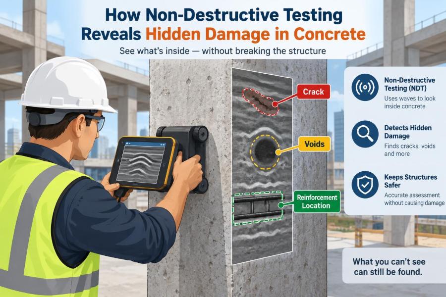

A parking structure may look sound from ground level while moisture, corrosion, and internal cracking are already reducing its durability. A bridge pier can show only a faint surface stain, yet contain voids or poorly consolidated concrete behind the cover.
Cutting cores or breaking open a slab can reveal the truth, but it also damages the asset and samples only a very small area. Engineers therefore need ways to investigate broadly before deciding where intrusive work is justified.
This is the role of non-destructive testing, usually shortened to NDT. It uses physical responses—such as sound, electromagnetic fields, heat, or electrical current—to identify changes inside or near the surface of concrete.
NDT does not provide a magic image of a structure’s condition. Used thoughtfully with drawings, visual inspection, and engineering judgement, however, it turns hidden conditions into evidence that can support safer, more targeted decisions. 🧰
🔎 1. What non-destructive testing means
Non-destructive testing examines a material or element without significantly impairing its present or future use. In concrete work, the term often includes non-invasive methods that leave no mark and minor-impact methods that make a small surface indentation.
The objective is not merely to collect readings. It is to infer conditions such as cracking, delamination, variable quality, reinforcement location, moisture, or possible corrosion activity.
A test is useful only when its result is connected to a clear engineering question. “Where is the likely defect?” is more valuable than “What number did the instrument display?”
🏗️ 2. Why hidden damage is difficult to assess
Concrete is heterogeneous. Aggregate particles, paste, pores, reinforcement, ducts, and construction interfaces all affect how energy or current moves through it.
Many important defects are also concealed by sound-looking cover concrete. A delamination may be parallel to the surface, an internal crack may be narrow, and reinforcement corrosion may begin long before spalling becomes visible.
Surface appearance still matters, but it cannot answer every question. NDT helps extend the investigation below the visible face without immediately removing material.
🧭 3. Start with the engineering question
Method selection should begin with a decision that needs to be made. Is the concern shallow delamination in a bridge deck, unknown bar layout before drilling, or possible internal voiding in a thick member?
- Define the suspected mechanism and likely defect depth.
- Identify access limits, geometry, and the required survey coverage.
- Decide whether the result will screen areas, locate features, estimate a property, or verify repair quality.
- Specify what follow-up evidence would confirm the interpretation.
A technique that is excellent for locating reinforcement may be poorly suited to evaluating a deep internal crack.
👀 4. Visual inspection remains the foundation
Visual inspection is the first NDT tool because it establishes context. Engineers map cracks, stains, efflorescence, rust marks, pop-outs, previous repairs, drainage paths, and deformation.
Crack width and pattern can suggest restraint, shrinkage, settlement, overload, corrosion, or chemical distress, but they do not prove the cause by themselves. Notes should record location, orientation, extent, and environmental exposure.
A carefully prepared defect map also makes later instrument data far easier to interpret. Measurements should be tied to a grid, coordinates, member faces, and photographs where appropriate.
🔨 5. Sounding identifies near-surface delamination
Sounding involves lightly tapping concrete with a hammer, chain, or similar tool and listening for changes in response. Sound concrete generally produces a sharper, more solid sound than a detached or delaminated layer.
The method is especially useful for rapid surveys of accessible surfaces. It can identify zones that warrant repair investigation or more detailed testing.
Its limitations are important: results depend on operator experience, surface condition, element thickness, and background noise. Sounding is best treated as a screening method, not a precise measure of defect depth or structural capacity.
📡 6. Ground-penetrating radar maps embedded features
Ground-penetrating radar, or GPR, transmits electromagnetic pulses into concrete and records reflections caused by changes in electrical properties. Reinforcement, conduits, layer interfaces, moisture changes, and some voids can create detectable responses.
For reinforced concrete, GPR is commonly used to locate bars, estimate cover, identify tendon paths, and reduce the risk of striking embedded items during coring or drilling.
Signal penetration depends strongly on concrete conductivity. Wet or chloride-contaminated concrete may attenuate the signal, and dense reinforcement can obscure features below the first reinforcement layer.
🧲 7. Cover meters locate reinforcement near the surface
Electromagnetic cover meters detect the influence of ferromagnetic reinforcement. They are fast, portable, and well suited to finding individual bars close to an accessible surface.
They can support cover surveys, bar-spacing checks, and safe planning of small openings. Their readings become less reliable with increasing depth, closely spaced bars, large bar diameters, or multiple reinforcement layers.
A cover meter does not directly assess corrosion or bond condition. It indicates the likely presence and approximate location of steel, which is valuable information for many other tests.
🌊 8. Ultrasonic pulse velocity examines wave travel
Ultrasonic pulse velocity, often called UPV, measures the travel time of a stress wave between transducers. A longer travel time may result from a longer path, lower wave velocity, cracking, voids, poor contact, or different material properties.
Measurements may be made directly through a member, semi-directly around a corner, or indirectly along one surface. Direct transmission usually offers the clearest path, but access to opposite faces is not always available.
UPV is highly informative when comparing similar locations under consistent conditions. A single velocity value should not be treated as a universal statement of concrete strength or quality.
🎧 9. Impact-echo uses reflected stress waves
Impact-echo introduces a short mechanical impact and analyzes stress waves reflected by boundaries. Reflections can arise from the back wall of a slab, a void, a delamination, or another internal interface.
The method can be particularly useful for investigating thickness, tendon duct grouting concerns, and planar defects. Its interpretation requires attention to geometry and expected wave modes.
Complex reinforcement, irregular shapes, and multiple interfaces may produce overlapping signals. Experienced interpretation and confirmation at selected locations are therefore essential.
🪨 10. The rebound hammer measures surface response
A rebound hammer records the rebound of a spring-driven mass after it strikes the surface. The rebound number reflects near-surface hardness and is affected by smoothness, moisture, carbonation, aggregate type, orientation, and local damage.
It is useful for identifying relative variability across a member or comparing areas tested under similar conditions. It may also help select locations for further investigation.
It should not be used alone to declare in-place compressive strength. Reliable strength estimation requires an appropriate correlation for the actual concrete and often verification with other evidence.
⚡ 11. Electrical methods investigate moisture and corrosion conditions
Electrical measurements can reveal conditions that influence reinforcement corrosion. Common approaches include surface resistivity and half-cell potential mapping.
Surface resistivity reflects how easily electrical current passes through near-surface concrete. Lower resistivity can be associated with higher moisture and ionic content, conditions that may support corrosion, but it is not a direct corrosion-rate measurement.
Half-cell potential compares the electrical potential of reinforcement with a reference electrode. It indicates the likelihood of active corrosion conditions in mapped areas, provided there is an electrical connection to the steel and suitable interpretation of the environment.
🗺️ 12. Condition maps reveal patterns, not just points
One reading can be misleading; a grid of readings can reveal a pattern. Engineers commonly plot sounding results, cover depth, resistivity, potential, UPV, or radar reflections on a plan or elevation.
Maps help relate anomalies to joints, drains, cracks, repairs, traffic lanes, or exposure zones. They also make it easier to define repair boundaries and prioritize areas for confirmation.
Spacing should match the expected defect size. A wide grid can miss small localized defects, while an extremely tight grid can consume resources without improving the decision.
🌡️ 13. Infrared thermography detects thermal contrasts
Infrared thermography measures surface temperature patterns. A shallow delamination, void, wet area, or different material can alter heat flow and create a temperature contrast at the surface.
Thermal surveys depend on an adequate heating or cooling cycle, surface exposure, wind, cloud cover, and the timing of measurement. The same defect may be more visible at one time of day than another.
Thermography is efficient for broad screening, particularly on large accessible faces. It detects thermal anomalies, however, not defects directly; shadows, surface moisture, and material changes can create false indications.
💧 14. Moisture changes nearly every interpretation
Water has a major influence on concrete testing. It can increase electrical conductivity, alter radar signal attenuation, affect rebound response, and change ultrasonic wave transmission.
Moisture may itself be the concern, especially near leaking joints or failed waterproofing. But it can also mask or imitate another condition if the survey team does not record recent rain, drainage, curing, or wetting history.
Testing records should note surface condition and environmental conditions. Comparing readings taken after different weather events without context can lead to incorrect conclusions.
🧪 15. NDT and destructive testing work together
NDT is often described in contrast to coring, petrography, chloride analysis, or pull-off testing. In practice, the strongest investigations combine both forms of evidence.
NDT can scan a large area and identify representative, critical, or anomalous locations. Limited intrusive tests can then verify material condition, establish depth, identify mechanisms, or calibrate an indirect measurement.
This combination reduces unnecessary damage while avoiding overconfidence in indirect signals. A core taken at a carefully selected anomaly is usually more informative than a core taken at random.
📊 16. A comparison of common concrete NDT methods
| Method | Typical information | Main strength | Important limitation |
|---|---|---|---|
| Sounding | Likely shallow delamination | Fast accessible-area screening | Subjective and depth-limited |
| GPR | Rebar, cover, interfaces, possible anomalies | Rapid mapping over large areas | Signal reduced by conductive or wet concrete |
| UPV | Wave-travel variation and continuity | Useful comparative quality assessment | Strongly affected by path and moisture |
| Impact-echo | Thickness and internal reflecting interfaces | Can target planar internal defects | Interpretation can be complex |
| Electrical mapping | Corrosion-related environmental conditions | Supports corrosion-risk zoning | Does not directly quantify section loss |
| Thermography | Near-surface thermal anomalies | Efficient broad-area survey | Weather and timing dependent |
The best method depends on the defect, access, and decision needed. A complementary combination is often more reliable than any single technique.
🧩 17. Multiple methods reduce ambiguity
Different methods respond to different physical properties. This is an advantage when their results are interpreted together rather than treated as competing answers.
For example, a hollow sounding response and a thermal anomaly in the same deck zone strengthen the case for a shallow delamination. Radar can then help identify reinforcement geometry before removal or repair.
Agreement does not automatically prove a diagnosis, but independent evidence increases confidence. Disagreement is also useful because it may reveal that an assumed defect mechanism is incomplete.
📏 18. Resolution, depth, and coverage must be balanced
Every survey involves trade-offs. Higher resolution may require closer measurement spacing, slower scanning, or shallower penetration; deeper investigation may produce less distinct detail.
Survey design should state the target depth range and smallest meaningful defect size. It should also recognize areas where access, coatings, reinforcement congestion, or geometry will limit data quality.
A broad first-pass survey followed by focused testing is often efficient. It avoids spending equal effort on areas that show no evidence of distress.
🧱 19. Reinforcement can help and hinder the test
Steel reinforcement is frequently the object of the investigation, yet it changes the signal received by many instruments. Radar reflections from bars can conceal deeper features, and ultrasonic paths may be affected by steel’s different wave velocity.
Rebar layout should therefore be established whenever possible before interpreting other data. Drawings are useful, but field verification matters because placement can differ from design intent.
Prestressing steel, ducts, anchors, and embedded utilities require additional caution. Their presence affects both interpretation and the safety of any confirmatory drilling.
🧯 20. Common false conclusions to avoid
An anomaly is not automatically damage. It may result from a change in aggregate, thickness, surface finish, moisture, reinforcement, or test coupling.
- Do not equate a rebound number directly with structural strength.
- Do not interpret low resistivity as proof that steel has already lost significant section.
- Do not treat a radar reflection as a void without considering reinforcement and interfaces.
- Do not assume a clear surface means the interior is intact.
- Do not extend conclusions beyond the tested conditions and area.
Careful wording is part of sound engineering. “Consistent with,” “indicative of,” and “requires confirmation” are often more accurate than absolute claims.
🧹 21. Surface preparation affects data quality
Loose coatings, dirt, standing water, rough projections, and poor transducer contact can degrade measurements. Before testing, the team should decide what preparation is permitted without altering the condition being investigated.
For wave-based methods, coupling material and consistent contact pressure can be important. For electrical methods, surface moisture and electrode contact must be controlled and documented.
Preparation also includes safe access. A technically capable method is of little value if it requires unsafe work near traffic, edges, live equipment, or unstable concrete.
📐 22. Calibration and reference areas provide context
Instrument checks verify that equipment is functioning, but field calibration provides context for the structure under investigation. Where possible, compare suspect zones with nearby areas known or reasonably expected to be sound.
Reference areas should have similar geometry, exposure, age, and surface condition. Comparing a wet repair patch with dry original concrete may identify a material difference rather than damage.
When an NDT value will inform a material-property estimate, correlations must be appropriate to the concrete and test arrangement. Generic charts cannot replace project-specific validation.
📝 23. Good documentation makes results defensible
A useful NDT report explains what was tested, why it was tested, how data were collected, and what limitations apply. Raw data alone rarely communicate the engineering significance.
- Identify equipment, settings, calibration checks, and test dates.
- Show survey grids, coordinates, member orientation, and accessible areas.
- Record surface condition, weather, coatings, and observed defects.
- Present maps, representative signals, interpretation criteria, and uncertainty.
- Separate observations from conclusions and recommendations.
Clear records allow another engineer to understand the evidence later, including after repairs or changes in condition.
🧑🔧 24. Competence matters as much as equipment
Modern instruments can automate data collection, but they do not eliminate the need for trained operators and informed interpretation. The operator must recognize poor coupling, scan direction effects, unsuitable settings, and implausible results.
The engineer responsible for conclusions should understand the physical basis of the method and the structural implications of potential defects. This is especially important when results affect load restrictions, repair scope, or public safety.
Communication between inspectors, NDT specialists, contractors, and designers helps convert a signal into an appropriate action.
🏥 25. NDT supports condition-based maintenance
Owners can use repeated NDT surveys to monitor condition over time. Instead of reacting only when spalls occur, they can identify developing patterns and plan investigation or repair before deterioration becomes extensive.
Trend data are most useful when testing locations, methods, and environmental conditions are reasonably consistent. A change in measurement may reflect a real condition change, but it may also reflect a changed procedure.
Condition-based maintenance does not mean testing everything continuously. It means directing attention toward exposure zones, known vulnerabilities, and consequences of failure.
🚧 26. NDT improves repair planning and verification
Before repair, NDT can help define unsound concrete beyond visibly spalled edges, locate reinforcement, and distinguish widespread deterioration from isolated damage. This supports realistic quantities and reduces avoidable removals.
During and after repair, selected methods can assist with checking bond-related anomalies, locating embedded items, verifying cover, or reviewing grout and concrete continuity where suitable.
No method substitutes for proper repair design, substrate preparation, material placement, curing, and inspection. NDT adds evidence at critical stages of that process.
🧠 27. The core principle: evidence before intervention
The central value of concrete NDT is not that it sees everything hidden inside a structure. Its value is that it gathers evidence across an asset with limited disruption, allowing engineers to focus intrusive investigation and repairs where they matter most.
Reliable conclusions come from a chain of reasoning: understand the structure and exposure, inspect visually, select methods matched to the question, control testing conditions, map patterns, and confirm significant findings when needed.
Non-destructive testing is most powerful when it is treated as disciplined investigation—not as a shortcut to certainty. Used with engineering judgement, it helps reveal hidden damage early enough to make better, safer decisions. 🔎🏗️🧰