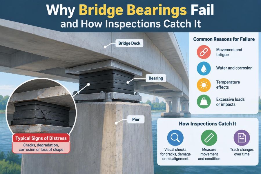

A bridge can appear completely ordinary from the roadway while a critical problem develops beneath the deck. Traffic keeps moving, the pavement may look sound, and the superstructure may show no obvious distress. Yet a bearing at one pier can be seized, displaced, corroded, or slowly losing its ability to carry load.
Bearings occupy a small physical space, but they control a major structural relationship: how the bridge deck transfers gravity loads to supports while still moving as temperature, traffic, creep, shrinkage, and settlement demand.
When that relationship breaks down, forces go somewhere else. They may accumulate in piers, abutments, diaphragms, deck joints, or girders that were not intended to resist them in that form.
This is why bearing inspection is not simply a matter of looking for rusty steel or cracked rubber. It is an exercise in understanding movement, load paths, detailing, exposure, and the warning signs that reveal a changing structural system. 🔍
🌉 1. What bridge bearings are meant to do
A bridge bearing is the component, or assembly of components, between a superstructure and a substructure. It transfers vertical reactions from the deck and girders into piers or abutments.
At the same time, many bearings permit controlled rotation, longitudinal movement, transverse movement, or a combination of these actions. The required freedom depends on the bridge layout and the bearing’s location.
Without bearings, ordinary bridge movements would have to be absorbed through deformation of the entire structural system. That can create unintended restraint forces and damage vulnerable details.
🧭 2. Why movement is a design requirement
Bridge movement is not a defect by itself. Materials expand and contract with temperature, concrete changes over time, and foundations can settle or rotate.
A continuous deck may also move differently from a simply supported span. The designer establishes a movement strategy by selecting fixed and expansion locations, bearing types, joint details, and restraint systems that work together.
Problems begin when the real bridge can no longer follow that strategy. A bearing that cannot slide, rotate, or deform as intended changes the boundary conditions of the structure.
⚖️ 3. The load path changes when a bearing fails
In its intended condition, a bearing provides a predictable path from girder to bearing plate, bearing body, pedestal, pier cap, pier, and foundation. The bearing also defines where horizontal forces are restrained and where movement is released.
If a sliding bearing locks, thermal movement may push against an abutment or pier. If an elastomeric bearing is badly distorted, its stiffness and geometry may alter how reactions are distributed among girders.
A bearing issue therefore deserves attention even when its damage appears local. Local deterioration can create system-level consequences.
🧱 4. The main families of bridge bearings
Different bearing types have different mechanisms, inspection needs, and failure patterns. An inspection begins by identifying what is actually installed, rather than assuming that all supports behave alike.
| Bearing family | Typical movement mechanism | Common inspection focus |
|---|---|---|
| Elastomeric | Rubber deformation and rotation | Bulging, cracking, delamination, misalignment |
| Steel rocker or roller | Rocking or rolling action | Corrosion, seized parts, tilt, missing restraint details |
| Pot bearing | Confined elastomer accommodates rotation | Seals, corrosion, tilt, plate condition |
| Spherical or disc | Curved or low-friction interfaces allow rotation and sliding | Sliding surfaces, guides, seals, displacement |
| Sliding plate | Low-friction interface permits translation | Debris, wear, lubricant condition where applicable, travel limit |
The names vary by project and era, but the inspection question is consistent: can the bearing still perform its specified actions safely?
🌡️ 5. Thermal movement is often the first test
Temperature changes cause bridge components to change length. For a long steel or concrete superstructure, even modest temperature variation can produce meaningful movement at expansion locations.
Bearings are often detailed to accommodate that movement. A sliding surface may travel, an elastomeric pad may shear, or a guided assembly may move in one direction while resisting another.
Evidence of blocked thermal movement includes compressed joints, contact between parts that should be separated, distorted guides, and unexpected cracking near restrained supports.
🚧 6. Installation errors can create a delayed failure
A bearing may be damaged or incorrectly positioned before the bridge ever opens. Incorrect elevation, skew alignment, orientation, preset position, anchor placement, or grout quality can all compromise performance.
For example, an expansion bearing installed near the end of its travel range may have little remaining capacity for seasonal movement in one direction. A bearing set out of square may experience unintended edge loading.
These errors can remain hidden until environmental cycles and traffic loading progressively expose them.
💧 7. Water is the recurring enemy
Water does not need to flood a bearing to cause harm. Repeated wetting, poor drainage, leaking deck joints, and runoff concentrated at a support can keep bearing components damp for long periods.
This accelerates corrosion of steel plates, anchor bolts, guides, and shims. It can also carry debris into sliding interfaces and degrade adjacent concrete pedestals.
An inspector should follow the water path, not merely inspect the bearing itself. A leaking joint directly above a support is often part of the root cause. 💧
🧂 8. Chlorides and corrosion work quietly
In regions exposed to deicing salts or marine environments, chloride-bearing moisture can intensify corrosion. Corrosion products occupy more volume than the original steel, so expansion can force plates apart, crack concrete, or lock closely fitted mechanisms.
Loss of metal section is equally important. Reduced thickness in a plate, guide, bolt, or weld region may decrease capacity even before movement becomes visibly restricted.
Corrosion assessment should consider both the visible surface condition and the likelihood of concealed deterioration at interfaces and embedded zones.
🧹 9. Debris can immobilize a movement system
Sand, leaves, road grit, bird nesting material, hardened runoff deposits, and maintenance debris can collect around a bearing. Where clearance is small, that material may physically block movement.
Debris also holds moisture against metal and conceals cracks or corrosion. A support that is difficult to access is especially likely to accumulate material for years without being cleaned.
Cleaning is not cosmetic work when the debris affects drainage, clearance, or sliding action. It can be a direct preservation measure.
🛞 10. Traffic loads reveal weak details
Bearings carry repeated load cycles as trucks cross a bridge. Although a bearing is designed for service actions, fatigue-sensitive attachments, loose anchorages, worn interfaces, and local plate bending can worsen under repeated loading.
Dynamic effects become more significant where the deck has rough approaches, damaged joints, or abrupt geometric changes. The bearing may then experience impact-like load variations beyond the smooth behavior assumed in normal service.
Inspectors should relate bearing distress to roadway condition, joint condition, and visible signs of deck movement.
🧩 11. Elastomeric bearings do not simply “wear out”
Elastomeric bearings accommodate rotation and movement through deformation of rubber layers, often reinforced with internal steel laminates. Their apparent simplicity can make them easy to overlook.
Useful observations include excessive bulging, cracking, splitting, extrusion, delamination, hardening, displacement from the sole plate, and uneven compression. Some deformation is expected, so the key is whether the observed shape is consistent with intended behavior.
A severely skewed or over-compressed pad may indicate excessive rotation, poor fit-up, unintended restraint, or a changed reaction pattern.
🔩 12. Steel bearings have vulnerable moving parts
Older steel rocker, roller, and pin-style bearings can remain functional for long periods, but they rely on geometry and freedom of movement. Corrosion, dirt, failed lubrication where relevant, and distortion can prevent their intended action.
A rocker that tilts excessively or a roller that no longer rolls may transfer horizontal force differently from the original design. Missing keeper plates or damaged guides can also create a stability concern.
Inspection should document orientation, contact, clearance, and apparent movement—not merely assign a general condition label.
🫧 13. Seals and sliding interfaces matter in modern bearings
Pot, disc, spherical, and guided sliding bearings often concentrate high loads within compact assemblies. Their performance can depend on seals, low-friction materials, polished or coated surfaces, and properly configured guides.
A damaged seal may allow contamination or loss of the protected condition needed for proper rotation. A fouled sliding interface may bind or develop uneven resistance.
Because some critical surfaces are concealed, external clues such as unusual tilt, limited travel, rust staining, debris accumulation, or displaced components become especially valuable.
📐 14. Misalignment creates edge loading
Bearings are intended to receive load over a defined contact area. If a girder, sole plate, masonry plate, or pedestal is misaligned, the reaction may concentrate near one edge.
Edge loading can lead to local yielding, uneven elastomer compression, plate distortion, cracking of grout, or spalling of the pedestal. On skewed bridges, geometric effects require particular care because movement and rotation do not always follow an intuitive direction.
Photographs taken square to bearing faces, combined with measured gaps and offsets, can make misalignment much easier to evaluate.
🏗️ 15. Settlement can be mistaken for a bearing problem
A bearing may appear tilted or displaced because the support beneath it has moved. Differential settlement, pier rotation, scour-related foundation effects, and pedestal deterioration can alter bearing geometry.
Conversely, a seized or damaged bearing can introduce forces that contribute to cracking at the support. The observed symptom does not automatically identify the cause.
Good inspection separates bearing distress from substructure movement, while recognizing that the two may be connected.
🧱 16. Pedestals, grout, and anchorages are part of the bearing system
The bearing is not an isolated object. Its load transfer depends on sound concrete, grout pads, anchor bolts, welds, sole plates, and bearing plates.
Cracked or spalled pedestals may reduce bearing area or expose reinforcing steel. Voids, crushed grout, loose anchors, and plate separation can signal that loads are not being transferred as intended.
An inspection record should include the condition of these adjacent details because repair decisions often depend on the whole support assembly.
👀 17. Start inspection with a broad visual scan
A systematic inspection typically begins before close contact. From a safe viewing location, inspect the overall line and level of girders, the relative position of deck and pier, drainage paths, joint leakage, and access constraints.
Then compare similar bearings across the bridge. A single bearing that looks markedly different from nearby units may deserve focused investigation.
Broad context prevents inspectors from treating each stain, crack, or offset as an isolated observation.
📏 18. Measure what the eye cannot judge reliably
Visual inspection identifies potential issues, but measurements make those observations useful. Simple tools can document gaps, bearing offsets, tilt, plate dimensions, crack widths, and available movement clearance.
For an expansion bearing, the observed position should be considered against the expected temperature condition and the intended travel range. A single measurement is informative; repeated measurements through time are often far more valuable.
Measurements should be repeatable, clearly referenced, and recorded with the date, location, and environmental context.
📸 19. Photographs should answer engineering questions
A useful bearing photograph does more than show that someone visited the site. It establishes which bearing is shown, its orientation, its relation to the girder and support, and the scale of visible distress.
- Take an overall support view before close-ups.
- Include a scale where practical and safe.
- Photograph both sides of the bearing when accessible.
- Capture drainage sources, joint leakage, and nearby cracks.
- Repeat views from consistent locations during later inspections.
Clear photo records allow engineers to distinguish active change from long-standing, stable conditions.
🗂️ 20. A bearing inventory prevents blind spots
Every bearing should have a unique location reference, such as span, line, support number, and girder position. The inventory should identify bearing type, apparent function, condition, observed movement state, and access limitations.
This matters on multi-girder bridges, where one support may contain many bearings with different exposure conditions. The exterior bearing below a leaking scupper may deteriorate very differently from an interior bearing at the same pier.
A well-organized inventory turns scattered observations into a manageable maintenance program.
🔎 21. Warning signs that deserve escalation
Not every defect requires the same response, but some observations warrant prompt engineering review because they may affect load transfer, stability, or movement capacity.
Examples of higher-concern observations
- Loss of bearing contact or obvious unseating risk.
- Severe tilt, displacement, or deformation.
- Fractured anchorages, plates, welds, guides, or restraint components.
- Extensive section loss or corrosion affecting critical parts.
- Concrete crushing, major spalling, or cracking at the pedestal.
- Evidence that movement is fully blocked at an expansion location.
The appropriate action depends on the bridge configuration and observed severity, but these conditions should not be dismissed as routine aging.
🧪 22. Close inspection may need specialized methods
Some conditions cannot be confirmed from a standard visual inspection. Access equipment, temporary traffic control, cleaning, measurements, survey work, or non-destructive examination may be needed to understand the detail.
Examples include checking concealed corrosion, confirming plate thickness, evaluating cracks in steel attachments, surveying support movement, or observing bearing response over a temperature range.
The method should answer a specific question. More data is helpful only when it improves the diagnosis or supports a repair decision.
🧠 23. Diagnosis requires a whole-bridge view
A cracked pedestal may result from concentrated bearing pressure, but it may also reflect freeze-thaw deterioration, poor original grout, or substructure movement. A closed expansion joint may point to a seized bearing, yet deck replacement details or debris could also be involved.
Engineers should test competing explanations against the evidence. Review drawings, past inspection reports, repair history, joint behavior, drainage, support geometry, and the condition of comparable bearings.
The best diagnosis explains both the damaged component and the structural behavior around it.
🛠️ 24. Repair must restore the intended behavior
Repair options range from drainage improvement and debris removal to local concrete repair, corrosion protection, bearing rehabilitation, or complete replacement. The correct option depends on the cause, not just the visible symptom.
Replacing a corroded bearing without stopping joint leakage may restart the same deterioration cycle. Freeing a seized bearing without assessing accumulated restraint effects may overlook damage elsewhere in the system.
For major work, the temporary load-transfer scheme is itself a critical engineering task. Jacking, support, sequence, stability, and movement control must be planned carefully.
🚦 25. Replacement work has construction risks
Bearings often support large reactions in confined spaces. During replacement, loads may be transferred through jacks and temporary supports while workers operate close to the load path.
Unexpected friction, locked-in forces, differential lifting, deteriorated concrete, and restricted access can complicate the work. Existing drawings may not fully reflect field conditions, especially on older bridges.
Preconstruction investigation and clear hold points help the team respond safely if actual bearing conditions differ from assumptions.
🌧️ 26. Prevention begins with details and maintenance
Durable bearing performance starts with design details that manage water, allow inspection access, provide appropriate clearances, and accommodate anticipated movement. It continues through construction quality control and routine maintenance.
Practical preventive actions include keeping drains functional, repairing leaking joints, removing debris, maintaining protective coatings where applicable, and documenting changes before they become severe.
A bearing hidden behind a diaphragm or above a difficult-to-reach pier cap may still be structurally vital. Access provisions make future inspection more reliable and less costly.
✅ 27. The core principle: preserve load transfer and movement
Bridge bearing failures are rarely just hardware problems. They are failures of a carefully designed interface between a moving superstructure and a supporting substructure.
Effective inspection looks for evidence that the interface is no longer transferring load, allowing rotation, accommodating movement, or resisting lateral actions in the intended way. It also traces water, corrosion, debris, geometry, and support condition back to their causes.
Catch bearing problems early by inspecting the entire support system, measuring change over time, and treating blocked movement as a structural warning—not a minor maintenance detail. 🌉🔍🛠️