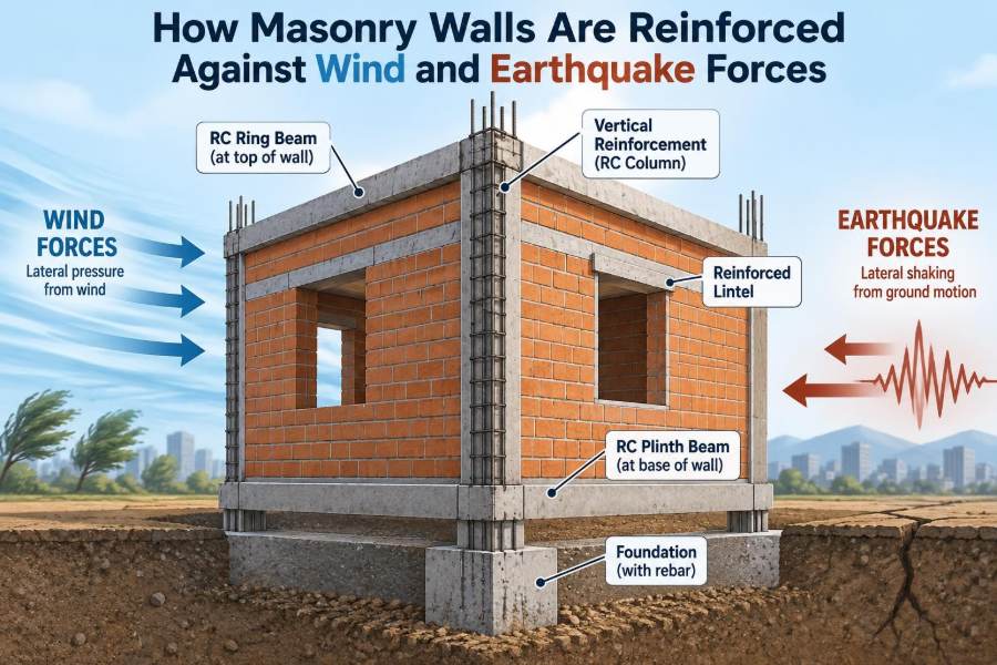

A brick or concrete masonry wall can look solid enough to resist anything. Yet severe wind and earthquake loading do not simply push on a wall once. They reverse direction, concentrate force around openings, shake connections loose, and test whether every part of the building can transfer load to the ground.
Consider a school gymnasium with long masonry walls, a low-rise apartment building with many window openings, or a warehouse with a tall perimeter wall. In each case, the wall may serve as enclosure, fire separation, architectural finish, structural support, or several of these functions at once.
When masonry is expected to resist lateral forces, its strength depends on much more than the compressive capacity of individual units. The system needs reinforcement, grouted cells, sound connections, deliberate detailing, and a continuous load path.
Understanding those elements helps engineers design safer buildings and helps construction professionals recognize why seemingly small details—such as a lap splice, anchor location, or bond beam—matter so much. 🧱
🌬️ 1. The Lateral-Load Challenge
Wind and earthquake forces are lateral loads: they act primarily sideways rather than vertically. Masonry performs very well in compression, but unreinforced masonry is relatively weak and brittle when tension, flexure, or repeated load reversal develops.
Reinforcement changes the wall’s behavior. Steel bars carry tensile forces after cracking, while masonry and grout provide compressive resistance, cover, stiffness, and confinement for the steel.
🏗️ 2. A Wall Is Part of a Larger System
A reinforced masonry wall does not resist lateral force in isolation. Floors, roofs, foundations, collectors, diaphragms, anchors, and adjacent walls all affect how force reaches and leaves the wall.
The central design question is simple: where does the lateral force go? A complete answer traces the force from the wind-exposed surface or moving mass through the building and ultimately into the supporting soil.
🧭 3. Following the Load Path
A continuous load path is the connected route through which forces travel. If one connection is weak, missing, or poorly detailed, a strong wall elsewhere cannot compensate for that break in the chain.
- Wind pressure acts on exterior cladding and walls.
- Roof and floor diaphragms collect and distribute that force.
- Shear walls and frames transfer it downward.
- Foundations spread the resulting shear, overturning, and uplift effects into the ground.
Earthquake loading follows a related route, but begins with the inertia of the building’s own mass. ⚙️
🌪️ 4. How Wind Loads Act on Masonry
Wind can apply inward pressure on a windward wall and suction on sidewalls, leeward walls, roof edges, corners, and parapets. Local pressures near corners and discontinuities can be especially important for wall panels, connectors, and coping.
For masonry, wind may cause out-of-plane bending of a wall panel or in-plane shear in a wall that braces the building. The governing condition depends on geometry, support conditions, openings, exposure, and the structural system.
🌎 5. How Earthquake Loads Differ
During an earthquake, the ground moves first and the building mass resists that motion because of inertia. The resulting forces can reverse rapidly, so a wall may cycle between tension and compression or between opposite shear directions.
This repeated loading is why earthquake design places strong emphasis on ductility. A ductile system can deform and dissipate energy while retaining meaningful strength, rather than failing suddenly after initial cracking.
🧱 6. Reinforced and Unreinforced Masonry
Unreinforced masonry relies mainly on unit strength, mortar, wall weight, and compressive stress. It may be suitable for limited applications under appropriate conditions, but it has restricted ability to accommodate tensile cracking and cyclic deformation.
Reinforced masonry includes steel reinforcement embedded in grouted cells or joints. This combination allows the wall to resist greater flexural tension, shear-related demands, and deformation while maintaining a more predictable load-resisting mechanism.
📏 7. In-Plane Versus Out-of-Plane Action
A wall loaded in plane acts much like a deep vertical cantilever or plate within its own surface. It can resist shear and overturning as part of the building’s lateral-force-resisting system.
A wall loaded out of plane bends perpendicular to its face, like a vertical or horizontal spanning panel. A single wall may need to resist both actions, and its connections must support both load paths.
| Wall action | Typical source | Primary concerns |
|---|---|---|
| In-plane | Diaphragm-delivered wind or seismic force | Shear, overturning, sliding, boundary forces |
| Out-of-plane | Wind pressure, wall inertia, impact of diaphragm movement | Flexure, anchorage, panel stability, support spacing |
🧩 8. What Reinforcement Actually Does
Steel reinforcement is placed where tension may develop. As masonry cracks under flexure, properly developed bars bridge the crack and resist tensile force, enabling the wall to continue carrying load.
Reinforcement also helps control crack width, ties portions of the wall together, and improves behavior under cyclic demand. It does not eliminate cracking; rather, it provides a controlled and reliable mechanism after cracking begins.
↕️ 9. Vertical Reinforcement for Flexure
Vertical bars are commonly placed in selected masonry cells and surrounded by grout. In a cantilevering shear wall, these bars are especially important near wall ends, where overturning can create high tension on one boundary.
For out-of-plane vertical spanning, vertical reinforcement resists bending generated by pressure on the wall face. Bar quantity, location, development, and the wall’s support conditions must all match the intended behavior.
↔️ 10. Horizontal Reinforcement for Distribution
Horizontal reinforcement can be provided through bond beams, reinforced bed joints, or other approved reinforcing arrangements. It helps distribute localized effects, contributes to flexural resistance for horizontally spanning panels, and assists with crack control.
Horizontal reinforcement is particularly valuable around openings and near diaphragm levels, where force transfer and stress concentrations can be significant.
🪨 11. Grout Makes the Composite System Work
Grout fills designated masonry cells around reinforcing bars. Once properly placed and consolidated, it bonds the steel and masonry together so they act as a composite structural element.
Grout must reach the intended location without harmful voids, segregation, or obstruction. Congested reinforcement, debris in cells, poor cleanout practice, and inadequate placement procedures can undermine a wall that appears correct on drawings.
🔩 12. Bond Beams Tie the Wall Together
A bond beam is a horizontal reinforced and grouted element within the masonry wall. It may occur at the top of a wall, at floor or roof lines, above openings, or at intermediate elevations.
Bond beams can collect diaphragm forces, distribute concentrated loads, tie intersecting walls together, support wall segments, and improve overall integrity. Their reinforcement must be continuous or properly spliced and anchored where continuity is required.
🪟 13. Openings Create Critical Regions
Doors, windows, vents, and large service penetrations interrupt the natural flow of force through a masonry wall. The remaining wall segments may become narrow piers, while masonry above an opening must span as a lintel or beam.
Engineers examine the jambs, lintels, and wall segments above and below openings carefully. Reinforcement is often concentrated there to carry redistributed forces and limit cracking at re-entrant corners.
📐 14. Shear Walls and Their Proportions
A masonry shear wall resists in-plane lateral force through a combination of shear strength, flexure, axial load effects, and reinforcement. Its height-to-length proportion influences whether its response is more flexure-dominated or shear-dominated.
Very slender walls tend to behave more like vertical cantilevers. Short, squat walls can develop high shear demand and require particular attention to diagonal cracking and shear-transfer mechanisms.
🌀 15. Understanding Shear Cracking
Shear cracking often appears diagonally because principal tensile stresses develop at an angle within the wall. Under earthquake load reversals, diagonal cracks may open in one direction and then the other.
Horizontal reinforcement, vertical reinforcement, masonry strength, grout quality, wall geometry, and axial compression all influence shear performance. Good seismic detailing aims to prevent brittle shear failure before the intended flexural mechanism can develop.
⚖️ 16. Overturning and Boundary Forces
When a shear wall resists lateral load, it develops an overturning moment. One end of the wall tends toward compression while the opposite end may develop tension and uplift.
These concentrated end demands are called boundary forces. Vertical reinforcement near wall ends, adequate grouting, robust foundations, and correctly designed anchorage are essential to transfer them safely.
🧲 17. Hold-Downs, Anchors, and Development
Tension reinforcement is useful only if its force can be developed and delivered into adjoining elements. At the wall base, this may involve bars extending into the foundation, mechanical anchorage where appropriate, or specially detailed connection assemblies.
At the top, wall reinforcement and anchors must connect effectively to the roof or floor system when the load path requires it. A bar terminated too soon, an inadequate splice, or a poorly anchored connector can govern the entire wall response.
🏠 18. Diaphragms Deliver Force to Walls
Roof and floor diaphragms act as horizontal structural elements. They collect lateral loads from broad areas of the building and transfer them to selected shear walls, frames, or other vertical resisting elements.
Wood, steel deck, and concrete diaphragms behave differently, but each needs connections capable of transferring the required shear. The wall-to-diaphragm interface is therefore one of the most important details in masonry construction.
🔗 19. Collectors and Chords Complete the Route
Not every wall lies directly beneath the load it must resist. Collectors, also called drag elements, transfer diaphragm forces toward a shear wall when the geometry of the building requires it.
Chords resist diaphragm tension and compression associated with overall bending. These elements may be hidden in framing, concrete, or steel, but their connections to masonry are indispensable to a coherent lateral system.
🧱 20. Veneer Is Not Automatically a Shear Wall
Masonry veneer is often an architectural cladding supported and laterally restrained by a backup wall or framing system. It should not be assumed to provide building shear resistance unless it has been specifically designed and detailed to do so.
Veneer still needs reliable anchors, support, movement accommodation, and out-of-plane restraint. Its own stability under wind and earthquake effects must be addressed independently from the primary structural frame.
📎 21. Ties, Anchors, and Out-of-Plane Stability
Wall ties and anchors resist forces between masonry and supporting construction. They must be selected and spaced for the expected demand, compatible with the materials they connect, and arranged so that they do not create unintended restraint or corrosion vulnerabilities.
For walls spanning out of plane, top, bottom, and side supports determine the effective span. The design must account for the actual ability of those supports to provide restraint, not just the restraint assumed in a simplified calculation.
🪜 22. Parapets Need Special Attention
Parapets project above the roof and are often exposed on both faces. Their unsupported height can make them vulnerable to out-of-plane wind pressure and earthquake inertia forces.
Reinforced, grouted construction; reliable attachment to the supporting wall or roof structure; and properly detailed coping all help manage this risk. A parapet should be treated as a structural element, not merely a decorative extension. ⚠️
🌡️ 23. Movement Joints Are Still Necessary
Reinforcement improves structural behavior, but it does not remove the need to accommodate thermal movement, shrinkage, moisture-related movement, and differential movement between materials. Movement joints help prevent random cracking caused by restrained dimensional change.
Joints must be located and detailed so they do not interrupt required structural load paths without an alternative connection. This is a coordination issue: architectural joint layouts and structural reinforcement layouts must work together.
🧱 24. Foundations Must Resist More Than Vertical Load
The base of a lateral wall transfers shear, compression, and often tension into the foundation. The foundation then must resist sliding, bearing pressure, overturning effects, and any uplift transmitted by the wall.
Reinforcing bars extending from wall to foundation must have adequate development. The foundation itself must be proportioned for the combined actions, including the effects of soil conditions and the building’s overall stability.
🧠 25. Capacity Design for Earthquake Resistance
Seismic design often seeks a preferred sequence of behavior. For example, a designer may intend flexural yielding in well-detailed reinforced wall regions while preventing brittle failure in shear, anchorage, splices, collectors, and foundations.
This philosophy is broadly known as capacity design. It recognizes that some inelastic response may occur during strong shaking and ensures that critical supporting components have sufficient reserve strength for that response.
🧾 26. Detailing Is as Important as Analysis
Structural analysis determines force demands, but detailing converts those demands into buildable reinforcement and connections. Drawings need to communicate bar locations, sizes, laps, hooks where required, grout lifts, bond beams, cleanouts, anchors, and interface details clearly.
Ambiguous drawings can lead to field improvisation, especially at crowded wall ends, openings, and roof connections. Early coordination with architects, contractors, and other disciplines is a practical form of risk reduction.
🔍 27. Inspection and Quality Control
Reinforced masonry depends on concealed work, so inspection matters. Before grout placement, inspectors and construction teams can verify cell cleanliness, bar position, lap locations, wall reinforcement, connectors, and access for grout placement.
During construction, attention is also given to unit placement, mortar workmanship, grout procedures, consolidation, and curing. Quality control does not replace sound design, but it confirms that the designed load path is actually being built.
🛠️ 28. Common Design and Construction Pitfalls
Many problems arise not from a lack of reinforcement, but from discontinuity. A wall can contain substantial steel and still perform poorly if the steel is not anchored, the grout is incomplete, or the diaphragm connection cannot transfer force.
- Treating a nonstructural partition or veneer as a lateral element without design verification.
- Interrupting reinforcement at openings without providing a clear alternate load path.
- Ignoring uplift and tension transfer at wall ends.
- Assuming nominal anchors provide seismic ductility without checking their behavior and connection details.
- Providing movement joints that unintentionally sever a required structural wall.
📚 29. A Practical Review Sequence
Students and professionals can use a repeatable sequence when reviewing a reinforced masonry lateral system. Begin with the building’s overall lateral scheme before focusing on individual bars or anchors.
- Identify wind and seismic load sources and directions.
- Locate diaphragms, shear walls, collectors, and foundations.
- Trace in-plane and out-of-plane load paths separately.
- Review openings, wall ends, parapets, and material interfaces.
- Confirm reinforcement continuity, development, grout requirements, and constructability.
This process encourages systems thinking rather than isolated component checks.
✅ 30. The Core Principle: Continuity Creates Resilience
Reinforced masonry resists wind and earthquake forces by combining masonry’s compressive strength with steel’s tensile capacity, then connecting both to diaphragms and foundations through a continuous load path. Vertical bars, horizontal reinforcement, grout, bond beams, anchors, and foundations each have a distinct role.
The most resilient design is not simply the one with more steel. It is the one in which every intended force has a clear route, every connection can deliver that force, and detailing supports stable behavior under the demands the building may face.
A masonry wall becomes dependable against lateral forces when reinforcement, grout, connections, diaphragms, and foundations act as one continuous structural system. 🧱🌬️🌎