
A hospital roof is being redesigned to carry new mechanical equipment. The plan looks simple: add supports, strengthen a few members, and verify the connections. But the real structure does not behave like a handful of isolated beams.
Loads find alternate paths. Steel and concrete restrain one another. Openings interrupt force flow, connections rotate, and a local stiffness change can shift demand into an unexpected part of the frame.
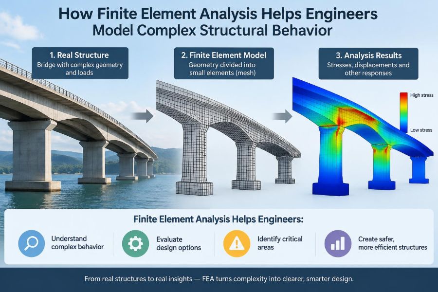
This is where finite element analysis, usually called FEA, becomes valuable. It gives engineers a practical way to represent a complicated structural system as many smaller, solvable pieces.
FEA is not a substitute for engineering judgment. Used well, it helps engineers see structural behavior more clearly, test design decisions efficiently, and focus detailed checks where they matter most. 📐
🧩 1. What Finite Element Analysis Actually Is
Finite element analysis is a numerical method for estimating how a structure responds to loads, restraints, temperature changes, movement, and other actions. The engineer divides a continuous object or structural system into a finite number of small elements.
Each element follows a mathematical relationship between displacement, deformation, and force. The analysis program assembles those individual relationships into a model of the complete structure.
The output may include deflections, support reactions, internal forces, stresses, strains, vibration properties, or stability indicators. These results are estimates whose reliability depends on the model and its assumptions.
🔍 2. Why Real Structures Are Difficult to Model
Elementary structural analysis often begins with idealized members: straight beams, pin-jointed trusses, or columns with simple end conditions. These idealizations remain useful, but many projects contain features that do not fit neatly into a one-dimensional calculation.
Examples include irregular floor plates, curved shells, transfer structures, deep openings, stiff cores, complex connections, and foundations interacting with flexible soil. A local detail can influence the behavior of an entire load path.
FEA allows the engineer to represent geometry and stiffness with more continuity, while still keeping the model computationally manageable.
🧱 3. The Core Idea: Discretizing a Structure
Discretization means replacing a continuous structure with a collection of connected elements. The connection points are called nodes, and the set of elements is called a mesh.
Instead of solving the exact differential equations at every point in a slab or wall, FEA calculates the response at nodes and interpolates behavior within each element. Smaller elements can capture more localized changes, although simply making every element tiny is not automatically good modeling.
The chosen mesh should reflect the structural question being asked. A global drift study and a connection stress study need very different levels of detail.
📍 4. Nodes, Degrees of Freedom, and Connectivity
A node is more than a point on a drawing. It is a location where the model tracks one or more possible movements, known as degrees of freedom.
In a planar frame, a node may translate horizontally and vertically and rotate. In a three-dimensional model, it may have three translations and three rotations, depending on the element formulation.
Connectivity determines which nodes belong to each element. If intended connections are missing, parts of the model may be disconnected; if unintended connections are created, the model may become artificially stiff.
📏 5. Selecting the Right Element Type
Element selection is one of the most important modeling decisions. An element should represent the dominant behavior of the physical component without adding unnecessary complexity.
| Element type | Common structural use | Primary behavior represented |
|---|---|---|
| Bar or truss | Bracing and idealized truss members | Axial force |
| Beam or frame | Beams, columns, portal frames | Axial force, shear, bending, torsion |
| Shell or plate | Slabs, walls, tanks, folded plates | In-plane and out-of-plane action |
| Solid | Thick regions, anchors, local details | Three-dimensional stress states |
| Spring or link | Supports, bearings, joints, soil idealizations | Specified force-displacement behavior |
A model can combine several element types. For example, a building model may use frame elements for columns, shell elements for core walls, and springs at foundation locations.
🏗️ 6. Modeling Material Behavior
Materials are often modeled initially as linear elastic. In that approximation, stress is proportional to strain, and the material returns to its original form when unloaded.
This is efficient and appropriate for many service-level analyses. However, it may not represent yielding steel, cracking concrete, crushing, contact, or permanent deformation.
For those situations, engineers may use nonlinear material models. These require credible material data, careful interpretation, and a clear purpose; complexity without validation can create false confidence.
🧭 7. Boundary Conditions Define Structural Reality
Boundary conditions describe what prevents movement. They represent supports, foundations, adjacent construction, symmetry planes, restraints, and connection behavior.
A fixed support, pinned support, roller, elastic spring, and sliding bearing all produce different reactions and internal forces. An unrealistic restraint can distort the model more severely than a rough estimate of loading.
Engineers should ask a direct physical question: what movement is actually prevented, and by what mechanism? That question often exposes modeling assumptions hidden behind a simple support symbol.
🔗 8. Connections Are Rarely Perfect Pins or Fixities
Textbook models commonly assume either pinned or fully rigid joints. Actual connections usually fall somewhere between those extremes.
A bolted end plate, a welded moment connection, a precast bearing, and a reinforced-concrete beam-column joint each have different stiffness, strength, and deformation capacity. Their behavior may also change as load increases.
FEA can represent connection flexibility with rotational springs, link elements, detailed solid models, or calibrated joint properties. The appropriate choice depends on whether connection response affects the design question.
🪜 9. Load Paths Become Easier to See
A structure is safe only if loads have a continuous route to the ground. Gravity loads may travel from slab to beam, beam to girder, girder to column, and column to foundation, but the route is often less obvious in irregular structures.
FEA reveals this through reactions, member forces, stress patterns, and deformation shapes. It can show when a stiff wall attracts lateral load, when a transfer element becomes heavily loaded, or when a diaphragm directs force around an opening.
Results should confirm a load path that the engineer can explain in words and sketch by hand.
🌬️ 10. Applying Loads Without Distorting the Model
Loads must be applied where and how they act physically. A distributed slab load placed directly onto a few beams may bypass the slab behavior that should distribute it.
Common loading categories include:
- Permanent gravity loads from structural and nonstructural components.
- Variable occupancy, storage, or maintenance loads.
- Wind, seismic, snow, earth, fluid, and construction actions.
- Temperature, shrinkage, settlement, prestress, and imposed displacement effects.
The model should also distinguish between forces and imposed movements. A support settlement is not simply another vertical force.
🧮 11. Linear Static Analysis Is the Starting Point
In a linear static analysis, stiffness is assumed constant, deformations are assumed small, and loads are typically applied without changing the structural configuration. The governing relationship can be expressed conceptually as [K]{u} = {F}.
Here, [K] is the stiffness matrix, {u} is the displacement vector, and {F} is the load vector. Once displacements are found, element forces and stresses can be calculated.
This approach is fast, transparent, and extremely useful. It is also limited: it cannot by itself capture behavior driven by major geometry changes, yielding, contact, or changing support conditions.
📉 12. Geometric Nonlinearity and Second-Order Effects
Geometric nonlinearity matters when deformed shape significantly affects equilibrium. A compressed column that laterally deflects develops additional moment because its axial load acts through the displaced geometry.
This familiar P-delta effect can be important in slender frames, flexible bracing systems, cable-supported structures, and members near instability. Local curvature effects are sometimes distinguished from frame-level sway effects.
Nonlinear geometry analysis updates equilibrium as the structure deforms. Engineers must still determine whether the model captures the relevant imperfections, restraints, and load sequence.
⚙️ 13. Material Nonlinearity Captures Inelastic Response
Material nonlinearity describes stiffness changes caused by cracking, yielding, hardening, softening, or damage. Reinforced concrete is a common example because its tensile cracking and reinforcement response influence stiffness substantially.
Steel structures may require inelastic modeling for plastic hinge studies, residual capacity assessments, or advanced performance evaluations. The model may use concentrated hinges or distributed material response along a member.
Because nonlinear results depend strongly on parameters, acceptance criteria, and numerical settings, they should be developed by engineers who understand both the physics and the software formulation.
🧷 14. Contact, Gaps, and One-Way Supports
Some structural interfaces transmit compression but not tension. A bearing can lift off, a masonry interface can open, and a foundation may resist compression differently from uplift.
These conditions are represented through contact elements, gap elements, compression-only springs, or tension-only links. They introduce nonlinear behavior because the active load path changes as the structure moves.
Such features are valuable when they are physically justified. Adding contact everywhere without reliable geometry and interface properties can make a model difficult to solve and harder to verify.
🌊 15. Dynamic Analysis Goes Beyond Static Loads
Structures can respond dynamically when loads vary with time. Earthquake shaking, machinery, footfall, wind-induced motion, impact, and moving vehicles all involve inertia.
Dynamic FEA includes mass as well as stiffness and damping. The conceptual equation becomes [M]{a} + [C]{v} + [K]{u} = {F}(t), where mass, damping, and time-varying loading influence the response.
The model mass must be checked carefully. Missing mass, duplicated mass, or unrealistic mass distribution can invalidate a dynamic analysis even if the stiffness model looks correct.
🎵 16. Modal Analysis Identifies Natural Vibration Patterns
Modal analysis calculates a structure’s natural frequencies and corresponding mode shapes. A mode shape is a characteristic pattern in which the structure can vibrate.
These results help engineers understand whether a structure is relatively flexible, whether torsional behavior is important, and which components participate in dynamic movement. They are often used as input to more advanced seismic or vibration analyses.
A visually plausible mode shape is not enough. Engineers should check mass participation, restraint assumptions, and whether the modes correspond to the intended physical system.
🏢 17. Diaphragms Control How Buildings Share Lateral Load
Floors and roofs often act as diaphragms that collect lateral forces and distribute them to frames, walls, or braced lines. Their stiffness can strongly affect force distribution.
A rigid diaphragm idealization may be suitable for some compact, stiff floor systems. A semi-rigid shell model may be more appropriate where the floor has large openings, irregular geometry, flexible deck behavior, or significant in-plane deformation.
The best representation is not the most detailed one. It is the one that captures the behavior relevant to lateral load transfer.
🕳️ 18. Openings and Discontinuities Create Stress Concentrations
Openings in slabs, walls, shells, and plates interrupt force flow. Loads must move around the opening, often concentrating forces near corners, edges, collectors, or supporting members.
FEA is particularly useful for visualizing these changes through contour plots and principal stress directions. It can identify where reinforcing, stiffeners, boundary elements, or local thickening may be needed.
However, singular peaks at a sharp re-entrant corner, point load, or idealized fixed edge may be mathematical artifacts. Engineers should evaluate stress patterns over a meaningful region rather than design directly from one extreme pixel value.
🗺️ 19. Mesh Density Must Match the Question
A mesh that is too coarse can miss bending curvature, stress gradients, and local load distribution. A mesh that is excessively fine increases run time, complicates review, and may magnify meaningless numerical peaks.
Good meshing uses smaller elements where response changes rapidly: near openings, concentrated loads, supports, abrupt thickness changes, and connection regions. More uniform regions can often use larger elements.
Mesh convergence is a practical check. The engineer refines the mesh and compares key results; if meaningful quantities stabilize, the model is becoming less sensitive to element size.
🔄 20. Compatibility and Equilibrium Are Essential Checks
A credible finite element model satisfies two central ideas. Equilibrium means applied loads are balanced by reactions and internal forces. Compatibility means connected components deform together in a physically consistent way.
Check total reactions against applied load, including moments where relevant. Then inspect the deformed shape for detached pieces, unexpected hinges, distorted diaphragm behavior, or supports moving in prohibited directions.
Many serious modeling errors can be found before reviewing a single stress contour.
🖥️ 21. Reading Deformed Shapes Before Contours
Contour plots are visually compelling, but the deformed shape is usually the first result to review. It provides a fast physical test of the model.
Ask whether the structure moves in the direction expected, whether supports behave correctly, and whether flexible and stiff components move relative to one another plausibly. Also note the displayed deformation scale, which is often exaggerated.
An attractive color plot cannot rescue an implausible displacement pattern. Start with motion, then move to forces, stresses, and design actions.
🎨 22. Contours Require Engineering Interpretation
Contours can display stress, strain, displacement, force resultants, or utilization measures. Their colors are not conclusions; they are a map requiring context.
Engineers should understand whether values are reported at integration points, averaged at nodes, extrapolated, or smoothed. Adjacent elements may show discontinuities that are physically meaningful or simply related to the chosen output method.
Review units, sign conventions, axes, legend limits, and load cases every time. A contour is only as useful as the quantity it represents.
🧠 23. Local Models and Global Models Serve Different Purposes
A global model captures overall load distribution, drift, stability, reactions, and member actions. It usually relies on simplified members, diaphragms, and connections.
A local model investigates a region such as a transfer girder opening, anchorage zone, base plate, corbel, or connection. It may use shell or solid elements and more detailed material assumptions.
The local model needs boundary conditions derived from the global behavior. Treating an isolated detail as though its boundaries are infinitely rigid can produce misleading local stresses.
🧪 24. Verification Is Different From Validation
Verification asks whether the mathematical model and software setup were implemented correctly. Examples include checking reactions, hand calculations, unit consistency, and mesh sensitivity.
Validation asks whether the model represents the real structure adequately for its purpose. This may involve comparison with test data, observed behavior, established analytical solutions, or previous reliable models.
Both matter. A perfectly solved model of the wrong physical system is not useful, and a physically sensible concept with implementation errors is not dependable.
✍️ 25. Hand Calculations Still Have a Central Role
FEA should extend engineering reasoning, not replace it. Simple calculations establish expected reactions, tributary loads, approximate deflections, buckling tendencies, and force paths before the software is opened.
These independent estimates create a range against which model results can be judged. A large discrepancy is not necessarily wrong, but it demands an explanation.
Useful checks include:
- Summing support reactions against total applied loads.
- Estimating beam moments and deflections with simplified boundary conditions.
- Comparing lateral stiffness and drift with rough frame or wall calculations.
- Checking whether force distribution follows relative stiffness expectations.
⚠️ 26. Common FEA Modeling Mistakes
Many errors arise not from difficult mathematics but from ordinary setup decisions made too quickly. A disciplined review process is the best defense.
- Using restraints that unintentionally prevent realistic movement.
- Applying loads to the wrong elements or duplicating self-weight.
- Assuming rigid offsets, diaphragms, or joints without checking their effect.
- Ignoring member orientation, local axes, releases, or eccentricity.
- Designing from isolated stress singularities.
- Trusting a successful solver message as proof of a correct model.
Software can solve an internally consistent but physically incorrect system very efficiently. ⚠️
📋 27. A Practical Workflow for Reliable Analysis
Reliable analysis is an iterative process, not a single software run. Begin with the structural question, then add complexity only when it improves the answer.
- Define the purpose: global force distribution, serviceability, vibration, stability, connection behavior, or another specific objective.
- Sketch expected load paths, supports, and likely governing behavior.
- Select appropriate element types, material properties, and boundary conditions.
- Apply loads and combinations consistently with the design basis.
- Run simple checks first, then inspect reactions and deformed shapes.
- Review forces, stresses, and displacements using independent calculations.
- Refine the mesh or assumptions where sensitivity is significant.
- Document assumptions, limitations, checks, and design decisions.
🛡️ 28. Documentation Makes Models Reviewable
An analysis model is part of the engineering record. Another engineer should be able to understand what it represents, what it omits, and how key decisions were checked.
Clear documentation includes model scope, geometry sources, material assumptions, support idealizations, loading approach, diaphragm assumptions, element choices, mesh strategy, and major verification results.
Annotated screenshots, reaction summaries, deformed shapes, and focused result plots are often more useful than an unfiltered stack of program output. Good documentation supports peer review and future modifications.
🌟 29. The Core Principle: Model Behavior, Not Just Geometry
The central value of finite element analysis is not that it produces colorful graphics or very large result files. Its value is that it helps engineers create a rational approximation of how stiffness, load, restraint, and deformation interact.
A useful model is as simple as possible but detailed enough for the decision at hand. It has a clear load path, defensible boundary conditions, appropriate element behavior, and results that agree with physical intuition and independent checks.
Finite element analysis becomes powerful when engineers use it to ask better structural questions, then verify that the answers make physical sense. 📐🔍🏗️