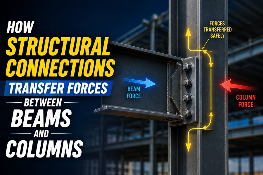

A building may appear to be made from separate beams, columns, slabs, and braces, but structurally these components must act together as one connected system. The points where members meet are called structural connections, and they play a critical role in transferring forces safely through the building. 🏢⚙️
A beam may carry the weight of a floor, but that force does not disappear at the end of the beam. It must pass through a connection into a column, wall, or another supporting member. Likewise, wind and earthquake forces may create bending moments and horizontal forces that must travel through joints before eventually reaching the foundations.
In steel, concrete, timber, and composite structures, connections determine how forces move from one part of the structure to another.
Understanding them is essential because even extremely strong beams and columns can fail if the connection between them cannot safely transmit the required forces. 🔩
🧱 What Is a Structural Connection?
A structural connection is the interface where two or more structural members are joined so that forces can pass between them.
Common examples include:
- Beam-to-column connections
- Beam-to-beam connections
- Column splices
- Brace connections
- Base plate connections
- Concrete beam-column joints
- Timber bolted or nailed joints
A connection may use components such as:
- Bolts 🔩
- Welds
- Steel plates
- Angles
- Reinforcing bars
- Anchor rods
- Screws
- Adhesives
- Bearing surfaces
The connection must be designed not only to hold the members together but also to transfer the specific types of forces acting on them.
⚖️ The Main Forces a Connection May Transfer
Structural members can experience several types of loading.
A connection may need to transfer:
⬇️ Shear Force
Shear tends to make one part of the connection slide past another.
Beam ends frequently transmit significant vertical shear into columns.
↩️ Bending Moment
A bending moment causes a member to curve.
Rigid beam-column connections may need to transfer substantial moments from beams into columns.
↔️ Axial Force
Axial force acts along the length of a structural member.
It may be:
- Tension
- Compression
Bracing systems often transfer large axial forces.
🔄 Torsion
Torsion attempts to twist a structural member.
Some edge beams, curved structures, transfer beams, and unusual framing arrangements can impose torsional forces on their connections.
Real connections may experience several of these forces simultaneously.
🏢 How Loads Travel Through a Building
Structural engineers often refer to the load path.
The load path describes how forces travel from where they are applied to the ground.
Consider a person standing on the fourth floor of a building.
Their weight may travel approximately through this sequence:
Person 👤
⬇️
Floor slab
⬇️
Floor beam
⬇️
Beam-to-column connection
⬇️
Column
⬇️
Foundation
⬇️
Soil 🌍
Every part of this chain must work.
If one connection cannot transmit the force into the next member, the load path becomes incomplete.
This is why connections are fundamental to structural safety.
🪵 A Simple Beam-to-Column Example
Imagine a steel beam supporting a floor.
The floor applies downward loading to the beam.
The beam bends under that load, and reactions develop at its supports.
At the beam end, the connection may need to transfer a vertical reaction into the column.
If the connection is designed primarily for this vertical reaction and allows beam-end rotation, it can behave approximately like a simple shear connection.
The force path could be:
Beam web → bolts or welds → connection plate → column
The plate, bolts, welds, beam web, and column must all have sufficient strength.
Failure of any one component could compromise the entire connection.
🔩 How Bolts Transfer Forces
Structural bolts are widely used in steel construction.
Depending on the connection design, bolts can transfer forces through mechanisms including:
🧱 Bearing
The bolt presses against the side of the hole in the connected steel plate.
This contact transfers force from one component to another.
✂️ Bolt Shear
The connected plates try to slide relative to each other, placing the bolt in shear across its cross-section.
🤝 Friction or Slip Resistance
In some pretensioned connections, bolts clamp the plates tightly together.
The clamping force creates friction between the plates.
Loads can then be transferred through friction before the plates slip.
Such connections can be important where movement at the joint must be limited.
🔥 How Welds Transfer Forces
Welding joins steel components by creating a continuous metallurgical connection.
Common structural weld types include:
- Fillet welds
- Groove welds
A weld may transfer:
- Shear
- Tension
- Compression
- Moment
- Combined stresses
For example, a steel plate welded to a column and bolted to a beam may transfer shear from the beam through:
Beam → bolts → plate → weld → column
Weld design must consider weld size, length, orientation, base metal strength, and force distribution.
Good workmanship and inspection are also important because weld quality affects structural performance.
🧠 What Is a Simple Connection?
In structural analysis, a simple connection is generally idealized as transferring shear while allowing significant rotation between the connected members.
Imagine a beam sitting between two columns.
As the beam bends downward, its ends rotate slightly.
A simple connection allows this rotation rather than strongly resisting it.
Typical steel examples can include:
- Shear tabs
- Double-angle connections
- Some seated connections
The idealized behavior is similar to a pin.
In practice, no connection is perfectly pinned, but some are flexible enough that engineers reasonably model them as such.
🏋️ What Is a Moment Connection?
A moment connection is designed to transfer substantial bending moment between members.
Instead of allowing a beam end to rotate freely, the connection restrains that rotation.
For a steel beam connected rigidly to a column, the beam’s bending moment can pass into the column through the joint.
This usually requires forces in both the beam flanges and web.
The top and bottom flanges may develop opposing tension and compression forces.
Because those forces are separated vertically, together they create a moment.
Conceptually:
Compression force → one flange
Tension force → opposite flange
The combination transfers the beam moment into the column. 🔄
📐 How a Moment Is Actually Transferred
A bending moment can be understood as a force couple.
Suppose a beam has a large moment near its end.
The beam’s top flange may be in tension while the bottom flange is in compression, or vice versa depending on loading direction.
The connection must carry those flange forces into the column.
The transferred moment can be approximated conceptually as:
Moment ≈ Force × Distance
The greater the distance between the opposing flange forces, the greater the moment that can be produced for a given force.
This is why flange connections are so important in steel moment frames.
🔧 Typical Steel Moment Connections
Steel moment connections may use:
- Welded beam flanges
- Bolted flange plates
- Extended end plates
- Haunches
- Reduced beam sections
- Stiffeners
The exact configuration depends on:
- Required strength
- Seismic requirements
- Fabrication method
- Construction sequence
- Member sizes
- Cost
In earthquake-resistant structures, connections may be designed not simply to remain perfectly elastic but to support controlled inelastic deformation without brittle failure.
🏗️ What Happens Inside the Column?
When a beam transfers large forces into a column, the column itself must distribute those forces.
For example, beam flange forces can create high local stresses in a steel column.
Engineers may need to check:
- Column flange bending
- Column web yielding
- Web crippling
- Panel-zone shear
- Local buckling
If the column is not strong enough locally, additional components such as continuity plates or stiffeners may be added.
The connection therefore includes more than bolts and welds—it also includes the behavior of the connected members around the joint.
🟦 The Panel Zone in Steel Frames
In a steel moment frame, the portion of the column web inside the beam-column joint is often called the panel zone.
When beams transfer moments into the column, large shear stresses can develop in this region.
During strong earthquakes, panel zones may undergo significant deformation.
Engineers must evaluate whether this behavior is acceptable.
In some structures, reinforcing plates called doubler plates may be added to strengthen the column web.
This illustrates an important principle:
Connection forces spread into surrounding structural material, not just through visible bolts or welds.
🧱 Reinforced Concrete Beam-Column Connections
In reinforced concrete structures, beams and columns are often cast together.
At first glance, this may look simpler because no obvious steel connection plate is visible.
However, force transfer still occurs inside the concrete and reinforcing bars.
A reinforced-concrete beam-column joint must transfer:
- Beam moments
- Beam shear
- Column forces
- Bond stresses
- Joint shear
Steel reinforcing bars run through or anchor into the joint.
The concrete provides compression resistance and confinement, while reinforcing steel carries significant tensile forces.
Proper detailing is critical. 🏗️
🔗 Reinforcement Anchorage
A reinforcing bar cannot simply stop wherever convenient.
Tension in the bar must be transferred into surrounding concrete through bond.
This requires sufficient development length or suitable anchorage.
At beam-column joints, reinforcing bars may be:
- Continued through the joint
- Bent
- Hooked
- Mechanically anchored
If anchorage is inadequate, the reinforcing bar can slip before reaching its intended strength.
Therefore, connection design in concrete is heavily influenced by reinforcement development and detailing.
🌎 Connections in Earthquake-Resistant Concrete Frames
Earthquakes subject beam-column joints to repeated reversals of force.
One moment may place the top beam reinforcement in tension.
A moment later, shaking may reverse direction and place the bottom reinforcement in tension.
This cyclic loading can be demanding.
Seismic concrete joints may therefore require:
- Closely spaced transverse reinforcement
- Strong confinement
- Adequate anchorage
- Careful joint dimensions
- Ductile reinforcement detailing
The goal is to prevent brittle joint failure while allowing controlled deformation elsewhere in the frame.
🌬️ How Wind Forces Reach Beam-Column Connections
Wind applies horizontal pressure to a building’s exterior.
That load must travel through the structural system.
A possible path is:
Building façade
➡️ Floor diaphragm
➡️ Moment frame or bracing
➡️ Beam-column connections
➡️ Columns
➡️ Foundation
In a moment-resisting frame, rigid beam-column connections play a major role in resisting sideways deformation.
As the building sways, beams and columns bend together.
Without connections capable of transferring moment, the frame would behave very differently.
🔺 Braced Frames Transfer Forces Differently
A braced frame uses diagonal members to resist lateral loads.
When wind or earthquakes act on the structure, braces mainly develop axial tension or compression.
These forces must pass through brace connections into beams and columns.
A typical brace connection may contain a gusset plate.
The load path can be:
Brace → bolts or welds → gusset plate → beam and/or column
Gusset plates must be designed for complex stress states and must often accommodate brace deformation, especially in seismic systems.
🔨 Timber Connections
Wood structures also rely heavily on connections.
Timber members may be joined using:
- Nails
- Screws
- Bolts
- Dowels
- Metal plates
- Engineered connectors
Force transfer often occurs through bearing between the fastener and wood.
Because wood is anisotropic—its properties differ along and across the grain—connection behavior depends strongly on fastener direction and geometry.
Engineers must consider failure modes such as:
- Wood splitting
- Fastener yielding
- Bearing failure
- Withdrawal
- Block shear
In timber design, connections can govern the strength and ductility of the entire structural system. 🌲
📐 Why Connection Stiffness Matters
Connection strength is not the only concern.
Stiffness also matters.
Two connections may both be strong enough to carry the required forces, yet behave very differently under load.
A flexible connection allows noticeable rotation.
A stiff connection restrains rotation and attracts larger moments.
Structural analysis therefore depends on realistic assumptions about connection behavior.
Connections are sometimes classified conceptually as:
- Simple
- Semi-rigid
- Rigid
In advanced analysis, actual moment-rotation behavior may be modeled rather than assuming perfect pins or perfect rigidity.
🔄 What Is a Semi-Rigid Connection?
Real connections often fall somewhere between perfectly pinned and perfectly fixed.
These are called semi-rigid connections.
They transfer some bending moment while still allowing rotation.
For example, a bolted end-plate connection may have enough stiffness to resist substantial moment but still deform under load.
Accounting for this behavior can improve the accuracy of structural models.
In many ordinary designs, however, engineers intentionally simplify the analysis using idealized connection categories that match the intended structural behavior.
💥 Common Connection Failure Modes
Structural connections can fail in many different ways.
Possible steel connection failures include:
- Bolt shear
- Bolt tension
- Plate bearing
- Plate yielding
- Plate rupture
- Block shear
- Weld fracture
- Local buckling
- Prying action
Concrete joints may experience:
- Joint shear failure
- Reinforcement pullout
- Bond failure
- Concrete crushing
- Poor confinement
Timber connections can experience:
- Splitting
- Fastener withdrawal
- Bearing failure
- Connector rupture
Connection design must consider all relevant limit states rather than checking just one component.
🧮 The Principle of Force Equilibrium
Every structural connection must satisfy equilibrium.
If a beam pushes downward on a connection with:
100 kN
then the connection must transfer an equal and opposite reaction into the supporting structure.
Likewise, if a beam end delivers:
200 kN·m of bending moment
that moment must be resisted through a corresponding system of forces.
The basic laws are:
ΣFx = 0
ΣFy = 0
ΣM = 0
These equilibrium equations are fundamental to connection design.
No force disappears at a joint—it must continue along a valid load path. ⚖️
🧠 Connection Design Is About Force Flow
A useful way to think like a structural engineer is to ask:
Where does the force go next?
For example, suppose a bolt carries 50 kN of shear.
Ask:
- How does the bolt receive that force?
- What plate does it bear against?
- How does the plate transfer the force?
- Where does the weld send it?
- Can the column accept it?
- How does the column carry it downward?
This concept is called force flow.
Good connection detailing creates a clear, reliable force path with minimal unintended stress concentrations.
🧲 Stress Concentrations
Connections often contain holes, weld ends, corners, and abrupt changes in geometry.
These features can create stress concentrations.
Stress near such regions may be much higher than a simple average calculation suggests.
Engineers account for this through:
- Design-code provisions
- Proper plate geometry
- Minimum edge distances
- Weld detailing
- Bolt spacing
- Smooth transitions
For highly complex connections, finite element analysis may be used to examine local stress behavior in greater detail.
📏 Why Bolt Spacing and Edge Distance Matter
Bolts cannot be placed arbitrarily close together or too close to the edge of a plate.
If a bolt is near a plate edge, the material between the bolt hole and edge may tear out.
If bolts are too close together, their stress fields can interact.
Structural codes therefore specify minimum values for:
- Bolt spacing
- Edge distance
- End distance
Proper spacing also helps ensure bolts can be installed and tightened during construction. 🔩
🔥 Shop Welding vs Field Welding
Steel structures are often fabricated partly in a workshop and assembled partly on-site.
Shop welding can offer advantages because conditions are controlled.
Field welding may be more difficult because of:
- Weather
- Access
- Positioning
- Inspection requirements
For this reason, a common strategy is:
Shop-weld components where practical
and
Field-bolt major assemblies
However, the exact construction method varies widely by project.
Connection design must account for how workers will actually fabricate and erect the structure.
🏗️ Constructability Matters
A theoretically perfect connection may be impractical if workers cannot install it.
Engineers must consider:
- Can a wrench reach the bolts?
- Can the welder access the joint?
- Will beams fit during erection?
- Are tolerances realistic?
- Can reinforcing bars physically fit inside the joint?
- Is inspection possible?
This is known as constructability.
Efficient structural design combines strength with practical fabrication and installation.
🌡️ Connections Must Accommodate Movement
Buildings move even under normal conditions.
Temperature changes cause materials to expand and contract.
Concrete shrinks.
Columns shorten under load.
Floors deflect.
Connections sometimes need to accommodate these movements.
For example, some beam connections may be designed to transfer vertical load while allowing small rotations or longitudinal movement.
Bridges often use bearings and expansion joints for similar reasons.
Making every joint completely rigid could unintentionally create large secondary forces.
🧯 Progressive Collapse and Connection Robustness
Connections can also contribute to structural robustness.
Suppose one column is unexpectedly damaged.
A robust structural system may redistribute loads through neighboring beams, columns, slabs, and connections.
Connections with adequate strength and ductility can help develop alternative load paths.
This can reduce the chance that a local failure spreads through a large portion of the building.
Design provisions for structural integrity therefore often consider continuity and connection capacity beyond ordinary everyday loading.
🪢 Why Ductility Is Important
A ductile connection can deform significantly before losing its ability to carry load.
A brittle connection may fail suddenly with little warning.
Ductility is particularly valuable during:
- Earthquakes
- Extreme loads
- Accidental events
In seismic steel frames, engineers often aim to ensure that designated members yield in controlled regions while critical connections remain capable of transmitting forces.
This idea is part of capacity design.
The structure is intentionally detailed so that predictable, ductile mechanisms occur before brittle ones.
🌍 Capacity Design in Earthquake Engineering
During a severe earthquake, preventing all yielding may be economically unrealistic.
Instead, engineers may allow certain structural regions to deform plastically and dissipate energy.
Connections must then be strong enough to transfer the forces generated by these yielding members.
For example, a moment frame might be designed around the principle:
Strong column + controlled beam yielding + reliable connection
The exact requirements depend on the structural system and design code.
This approach improves seismic resilience by directing damage toward intended ductile mechanisms.
🖥️ How Engineers Analyze Connections
Simple connections can often be designed using hand calculations and code equations.
More complicated connections may require:
- Structural analysis software
- Connection-design software
- Finite element analysis
- Nonlinear analysis
Computer models can simulate:
- Bolt forces
- Plate bending
- Weld stresses
- Contact behavior
- Local yielding
However, software does not replace engineering judgment.
The engineer must still understand the expected force path and realistic connection behavior.
🔍 Inspection Is Part of Connection Safety
Connections must not only be designed correctly—they must also be built correctly.
Inspection may involve checking:
- Bolt type and installation
- Bolt pretension
- Weld size
- Weld quality
- Plate dimensions
- Reinforcement placement
- Concrete consolidation
- Anchor locations
Methods for weld inspection may include:
- Visual inspection
- Ultrasonic testing
- Magnetic particle testing
- Radiographic methods
Inspection requirements depend on the project, connection type, governing standards, and risk level.
🏢 Why Connections Can Control the Entire Structural Design
In some structures, connection design becomes the deciding factor in member size.
A beam might have enough strength to carry its bending load, but connecting that beam efficiently to a small column may be difficult.
Likewise, a brace may be strong enough in tension but require a very large gusset plate to transfer its force.
Engineers must therefore think about connections early in the design rather than treating them as an afterthought.
Member design and connection design are closely linked.
🧩 Prefabrication and Modular Construction
Modern construction increasingly uses prefabricated structural components.
Entire wall panels, steel frames, or modular units may be built off-site and transported to the project.
In these systems, connections become especially important because modules must be joined rapidly and accurately.
Connections may need to provide:
- Structural strength
- Alignment
- Fast installation
- Repeated tolerances
- Sometimes demountability
Improved connection systems are helping make modular construction faster and more efficient. 🚚🏗️
🌉 Connections in Bridges
Bridge connections can experience especially demanding conditions.
They may be subjected to:
- Heavy truck loads
- Repeated fatigue cycles
- Temperature changes
- Wind
- Seismic loads
- Corrosion
Repeated loading makes fatigue a major concern.
A connection that is strong enough under one static load may still develop cracks after millions of stress cycles.
Bridge details therefore require careful consideration of weld geometry, bolt holes, stress ranges, and corrosion protection.
🔮 The Future of Structural Connections
Modern structural engineering is improving connections through:
- High-strength bolts
- Advanced welding methods
- Improved seismic detailing
- Prefabricated connection systems
- High-performance materials
- Digital fabrication
- Robotic welding 🤖
- Structural health monitoring
- 3D finite element modeling
Sensors may also be embedded in critical structures to monitor strain, displacement, bolt behavior, or vibration.
These technologies can help engineers evaluate how connections perform throughout the life of a structure.
🏁 Final Thoughts
Structural connections are the pathways that allow beams, columns, braces, slabs, and foundations to behave as a single structural system.
When a beam carries gravity load, its connection transfers that force into the supporting column. When wind pushes a building sideways, beam-column joints and bracing connections transmit those horizontal forces through the frame. During an earthquake, carefully detailed connections may need to withstand repeated reversals while allowing controlled deformation. 🏗️🌎
Different connections transfer forces in different ways:
Bolts can transfer force through shear, bearing, tension, or friction.
Welds create continuous force paths between steel components.
Reinforcing bars transfer tension through bond and anchorage in concrete.
Timber fasteners transfer forces through combinations of bearing and fastener action.
Some joints are intentionally flexible and mainly transmit shear. Others are designed to transmit significant bending moments and make beams and columns act almost continuously.
Whatever the material, the fundamental engineering question remains the same:
Where does the force go?
A safe connection provides a clear path from one member into the next without allowing bolts, welds, plates, reinforcement, concrete, timber, or surrounding members to fail prematurely.
That is why connections are often described as some of the most critical—and most carefully detailed—parts of a structure. Individual beams and columns may carry the visible loads, but it is the connections between them that allow the entire building to stand together. 🔩🏢✨