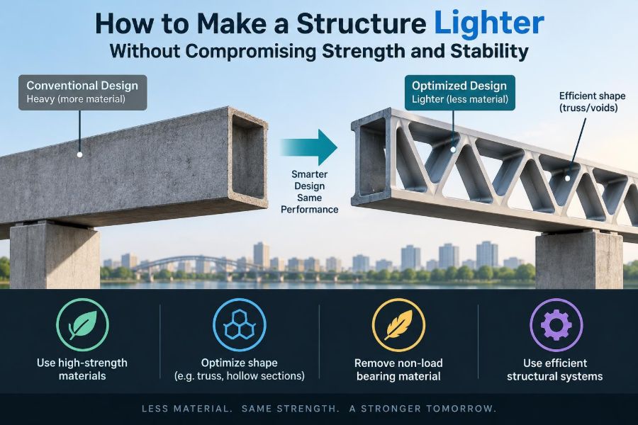

A pedestrian bridge needs to span a road without making the supports below excessively large. A roof must cover a wide hall without burying the building in deep beams. A vehicle chassis needs to resist impact and fatigue while carrying as little unnecessary mass as possible. These are all versions of the same engineering challenge.
Making a structure lighter is not simply a matter of removing material. Remove it from the wrong place and a member may buckle, deflect too much, vibrate uncomfortably, crack early, or fail a connection long before its calculated strength is reached.
The better question is: where does material actually do useful work? Structural engineering becomes efficient when geometry, load path, material behavior, detailing, and construction method are considered together rather than one at a time.
Lightweight design can reduce foundation demands, transport effort, embodied carbon, and sometimes cost. But it must always preserve a safe and reliable response to real loads, imperfect construction, environmental exposure, and changing use.
🎯 Start With Performance, Not Weight
A structure is not successful because it has the lowest possible mass. It is successful because it meets its required performance with no wasteful material, complexity, or risk.
Before optimizing anything, define the governing requirements: strength, serviceability, fire resistance, durability, robustness, vibration comfort, architectural constraints, and construction sequence. A floor that is strong enough but bounces noticeably under foot traffic has not met the full design brief.
Lightweight is a constrained design goal, not an isolated target. The allowable reduction in material depends on every limit state the structure must satisfy.
🧭 Trace the Complete Load Path
Every load needs a continuous route to the ground. For a typical building floor, gravity load travels from slab to beams, beams to girders or walls, then to columns, foundations, and soil.
When that route is direct, forces are usually easier to understand and members can be used efficiently. When loads must turn corners, transfer through offsets, or pass through flexible components, bending and local stresses tend to increase.
A useful early-design exercise is to sketch arrows showing the path of each major load case. Include vertical gravity loads, wind, earthquake actions where relevant, soil pressure, thermal movements, and construction loads.
📐 Use Geometry Before Adding Material
Changing shape can be more effective than increasing section size. A flat strip of steel bends easily in one direction, yet the same amount of steel formed into an I-section, channel, tube, or folded plate can resist bending far more effectively.
This is because bending resistance depends heavily on how far material is placed from the neutral axis, the zone in a bent member that experiences little or no longitudinal strain. Material near the outer fibers contributes much more to bending stiffness and strength.
In simple terms, do not concentrate all the material in the middle of a beam if the beam needs to resist bending. Put material where the stresses demand it.
📊 Distinguish Strength From Stiffness
Strength is the ability to avoid yielding, crushing, fracture, or another form of failure. Stiffness is the ability to resist deformation under load. They are related, but they are not interchangeable.
A slender high-strength steel member may have enough strength yet deflect too much. Increasing the steel grade does not significantly increase the elastic modulus, so it may not solve a deflection problem. A deeper section, different support arrangement, or composite action may be more effective.
| Design question | Primary concern | Common efficient response |
|---|---|---|
| Will the member fail? | Strength and stability | Improve section capacity, material grade, or load path |
| Will it sag too much? | Stiffness | Increase effective depth or reduce span |
| Will it sway or feel bouncy? | Dynamic behavior | Add stiffness, damping, mass distribution control, or bracing |
📏 Increase Effective Depth Where It Matters
For members governed by bending, depth is often an exceptionally powerful design variable. A deeper beam generally develops a larger internal lever arm between compression and tension forces, while its moment of inertia also increases markedly.
That does not mean every beam should be as deep as possible. Floor-to-floor height, service openings, fire protection, transport limits, and architectural appearance can constrain depth. The engineering opportunity is to place depth where bending moments are high and where it does not create new coordination problems.
Haunched beams, tapered girders, and variable-depth bridge sections use this principle by putting more depth near supports or other high-moment regions.
🔺 Let Triangles Carry Axial Force
A rectangle can distort into a parallelogram unless its corners are rigid or it is braced. A triangle is geometrically stable because its shape cannot change without changing the length of a side.
Trusses use triangulation to convert much of the load response into axial tension and compression rather than bending. Axial force generally uses material more efficiently, especially over long spans.
Trusses are not automatically lighter in every case. Their many members, joints, fabrication tolerances, corrosion protection needs, and connection forces must be considered. They are most valuable when their depth and geometry can be accommodated.
🌉 Match Structural Form to the Span
Short spans can often be served efficiently by slabs, joists, or simple beams. As spans grow, bending moments and deflections rise quickly, making deeper beams, girders, trusses, arches, cables, or shell-like systems more attractive.
An arch carries loads largely through compression but generates horizontal thrust at its supports. A cable carries tension efficiently but needs anchors and can be sensitive to movement. A truss needs depth but can keep material away from the lightly stressed center of a solid beam.
There is no universally lightest structural system. The best choice depends on span, support conditions, load pattern, available depth, construction method, and desired robustness.
🧱 Choose Materials for the Actual Demand
Material selection should consider more than nominal strength. Density, stiffness, ductility, fatigue behavior, corrosion resistance, fire performance, availability, connection method, and whole-life maintenance all influence whether a solution is truly efficient.
High-strength steel can reduce the area needed for tension-dominated elements. Concrete is often effective in compression and can provide mass, fire resistance, and durability. Timber can offer a favorable strength-to-weight ratio but requires careful moisture, connection, and fire design.
Using a stronger material where stiffness or buckling governs may produce little weight reduction. Select the material according to the governing action, not its marketing label.
🧩 Use Composite Action Intelligently
Composite action occurs when different components are connected so that they resist load together. A common example is a concrete slab acting with a steel beam through properly designed shear connectors.
The concrete works well in compression near the top of the composite beam, while the steel is efficient in tension near the bottom. The combined section can be stiffer and stronger than the two parts acting separately.
Composite behavior depends on reliable force transfer. If connectors, bond, reinforcement, or interface details are inadequate, the assumed efficiency may not develop. Construction sequence also matters because the steel beam may carry fresh concrete before the composite section becomes active.
🕳️ Remove Low-Stress Material Carefully
Holes, ribs, corrugations, cellular beams, and hollow sections can reduce mass by removing material from regions where it contributes less to the governing action. This is a familiar principle in aircraft components, fabricated steel beams, and ribbed concrete slabs.
But openings create stress concentrations and may reduce shear capacity, buckling resistance, fire performance, or fatigue life. Around an opening, force paths must detour, so the surrounding material may require reinforcement or stiffening.
A web opening in a beam is not merely an empty space for ducts. It is a local structural redesign that must be checked for the forces present at that location.
🌀 Design Against Buckling Early
Buckling is a stability failure in which a compression member suddenly deflects sideways, twists, wrinkles, or otherwise changes shape before its material strength is fully used. Slender columns, thin plates, and unbraced beam flanges are especially vulnerable.
This is why simply making a compression element thinner can be dangerous. Its weight may decrease gradually, while its buckling capacity can fall sharply once slenderness becomes excessive.
Efficient solutions include reducing unsupported length with bracing, using closed or stiffened sections, placing material away from the centroid, and avoiding unnecessarily thin plate elements. Stability checks should guide the initial geometry, not be left until the end.
🧷 Restrain Lateral-Torsional Buckling
A beam with an unrestrained compression flange can move sideways and twist as it bends. This behavior, called lateral-torsional buckling, can control the design of long steel beams even when their vertical bending strength seems adequate.
Floor slabs, purlins, cross-frames, diaphragms, and discrete braces can restrain the compression flange. The restraints must themselves be detailed to receive and transfer the stabilizing forces.
Assuming restraint without confirming the load path is a common error. A beam is only braced if the attached system has sufficient stiffness and strength to prevent the relevant movement.
🏢 Make Floors Work as Diaphragms
Floors and roofs often do more than carry gravity loads. A sufficiently stiff and connected deck can act as a diaphragm, collecting wind or seismic forces and distributing them to walls, frames, or braced bays.
Using the floor system efficiently can reduce the need for isolated, oversized lateral elements. However, diaphragm action depends on decking, slab reinforcement, fasteners, collectors, openings, and perimeter connections.
Large atriums, irregular plans, discontinuous decks, and major penetrations can interrupt this behavior. The assumed diaphragm model must reflect the physical construction rather than an idealized plan drawing.
🌬️ Control Wind and Seismic Drift
Lateral systems are often governed by drift, the horizontal displacement of a building under wind or earthquake action, rather than by member strength alone. Excessive drift can damage cladding, partitions, services, and finishes, or create occupant discomfort.
Braced frames, shear walls, moment frames, and cores each offer different balances of stiffness, architectural freedom, ductility, and construction complexity. Combining systems can be effective, but only if their relative stiffness and load sharing are understood.
A lighter gravity frame does not help if the lateral system becomes too flexible. The whole building must be assessed as an interacting structural system.
🔩 Treat Connections as Part of the Structure
Members rarely fail in isolation. Bolts, welds, plates, anchors, reinforcing bars, bearing zones, and interface details transfer forces from one component to the next.
An elegant lightweight member can require a bulky connection if large forces are concentrated at a small joint. That connection may dictate fabrication, erection sequence, inspection access, and local reinforcement.
Designers should ask early: can this force actually enter and leave the member? A consistent force path through connections is often what separates a theoretically efficient concept from a buildable one.
🧱 Avoid Overlooking Local Effects
Global analysis might show that a beam, column, or slab has acceptable overall capacity. Local effects can still govern near supports, point loads, anchors, openings, and abrupt changes in section.
For example, a thin steel web may buckle locally beneath a concentrated reaction. A flat concrete slab may be vulnerable to punching shear around a column. A timber member may split near a heavily loaded connection.
Lightweight design requires attention at these force-entry points. Local thickening, stiffeners, bearing plates, confinement reinforcement, or distributed connections can preserve efficiency without enlarging an entire member.
⚖️ Optimize Load Combinations, Not One Load
Structures experience different combinations of permanent loads, occupancy loads, snow, wind, temperature effects, equipment loads, and other actions. The condition that produces maximum bending may not produce maximum shear, uplift, compression, or lateral drift.
A lightweight design based only on a typical gravity load can miss the case that truly governs. For instance, wind uplift may control roof connections even where gravity loads control the roof framing.
Applicable design codes define load combinations and safety formats for a reason. The final design must satisfy the relevant combinations for its jurisdiction, material, occupancy, and hazard exposure.
📉 Reduce Loads at Their Source
The most efficient force is often the one that never reaches the structure. Choosing lighter façade systems, rationalizing heavy finishes, locating equipment near supports, and avoiding unnecessary permanent loads can reduce demands throughout the load path.
Self-weight is especially influential in long-span structures because it creates force in the members that are needed to carry the weight of those same members. This feedback can make a modest reduction in dead load valuable at several levels of the structure.
Load reduction should not compromise acoustic separation, fire performance, durability, or user needs. It is a coordinated architectural and engineering decision.
🏗️ Account for Construction-Stage Forces
A completed structure may be stable and efficient, yet become vulnerable during lifting, transport, temporary support removal, concrete placement, or partial erection. The structure must survive every realistic stage on the path to completion.
Precast panels may see different stresses when lifted than when installed. A steel frame may need temporary bracing before decks and diaphragms are in place. A composite beam has a different capacity before the slab hardens.
Ignoring these conditions can lead to excessive temporary works or, worse, instability. Early coordination with fabricators and contractors often reveals lightweight solutions that are practical to erect.
🛠️ Design for Fabrication and Tolerances
A member with a sophisticated variable shape may be structurally efficient but difficult to fabricate, inspect, transport, or fit on site. Added labor, weld length, specialized forms, and tight tolerances can outweigh a modest material saving.
Repetition is often a strong ally of efficient construction. Standardized member sizes, rational connection families, and accessible installation details can reduce waste and simplify quality control.
The goal is not to avoid complexity at all costs. It is to spend complexity where it produces a clear structural benefit, rather than creating fragile details that demand perfect site conditions.
🧪 Check Vibration and Dynamic Response
Low mass can make a structure more responsive to rhythmic or moving loads. Long-span floors may be strong and stiff enough under static checks but still feel uncomfortable when people walk, jump, or exercise on them.
Footbridges, grandstands, machine supports, and slender stair systems may also require dynamic assessment. Natural frequency, mode shape, damping, excitation frequency, and occupancy all affect the response.
Adding mass is not always the best remedy. Increasing stiffness, changing layout, introducing damping, or reducing the excitation mechanism may be more targeted solutions. Dynamic behavior should be considered early for structures likely to be sensitive.
🔥 Preserve Fire and Durability Performance
Material reduction can reduce protective cover, corrosion allowance, char depth reserve, or the size available for fire protection. A member that performs well at room temperature may lose capacity rapidly in a fire or after years in an aggressive environment.
Exposure conditions matter. Coastal air, de-icing salts, industrial chemicals, repeated wetting, ultraviolet radiation, and freeze-thaw cycles can change the appropriate detail and material choice.
Durability is a structural efficiency issue because replacement, strengthening, and repairs consume resources. A slightly heavier but long-lived detail can be more responsible than a minimal section that is difficult to maintain.
🛡️ Build in Robustness and Redundancy
Robustness is the ability of a structure to resist disproportionate collapse or severe damage after an unusual local event, such as accidental impact, loss of a support, or localized connection failure. It does not mean making every component massive.
Continuous ties, alternate load paths, ductile connections, compartmentalized systems, and clear detailing can help a structure redistribute load when one part is damaged. Some systems are inherently redundant; others rely heavily on a few critical components.
Extreme material efficiency should never eliminate the margin needed for realistic imperfections and unforeseen local damage. A light structure still needs a forgiving failure path.
🧮 Use Analysis Models With Judgment
Finite-element software can quickly analyze complex geometry, but a detailed model does not automatically produce a reliable answer. Results depend on boundary conditions, load application, element selection, connection assumptions, mesh quality, and interpretation.
Start with hand checks and simple models to estimate reactions, bending patterns, and expected deformations. Then use more advanced analysis to refine the design or investigate local behavior.
Unexpectedly low forces are not always good news. They may indicate a missing load, unintended release, unrealistically stiff support, or incomplete load path in the model.
🔍 Use Iteration Rather Than One-Pass Sizing
Efficient structures rarely appear in the first sizing attempt. A practical workflow moves repeatedly between structural form, member sizes, load estimates, coordination constraints, and constructability.
- Establish spans, supports, loads, and required performance.
- Select a structural form with a clear load path.
- Size members approximately and identify likely governing checks.
- Refine geometry, material placement, bracing, and connections.
- Check all relevant limit states, including construction stages.
- Coordinate the final system with architecture, services, and fabrication.
This process is not indecision. It is how engineers expose the trade-offs that a single calculation cannot reveal.
🚫 Avoid the “Thinner Everywhere” Mistake
One of the least reliable ways to reduce weight is to reduce every plate, bar, slab, and member by the same proportion. Different components are governed by different actions, so uniform thinning can move the problem from bending to buckling, vibration, connection capacity, or durability.
Another mistake is optimizing an isolated member while ignoring the supporting system. A lighter beam may increase deflection in a connection, transfer greater force into a column, or demand a heavier lateral restraint system.
Good optimization is selective. It removes or relocates material only after the governing behavior is understood.
💡 Learn From a Simple Beam Example
Consider a hypothetical long roof beam that is too heavy in its first design. Replacing it with higher-strength steel might reduce area if bending strength governs, but it may not reduce deflection enough.
Increasing its depth, adding a restraint to the compression flange, or changing it to a truss may reduce required steel more effectively. If services require openings, a cellular or castellated form might work, provided web-post buckling and local forces are checked.
The lesson is not that one solution is always best. It is that the engineer should identify the active constraint before choosing the tool.
🌱 Consider Whole-Life Efficiency
Less material can lower embodied impacts, but weight alone is not a complete environmental measure. Material production route, reuse potential, transport distance, maintenance, expected service life, and adaptability all matter.
A bolted steel system may be easier to disassemble and reuse than a highly integrated assembly. A durable concrete solution may have a different environmental profile from a lightweight system requiring frequent protective renewal.
Designing for future modification can also avoid demolition. Regular grids, accessible connections, and reserve capacity in carefully chosen locations can extend a structure’s useful life.
🤝 Coordinate Beyond the Structural Model
Architects, building-services engineers, geotechnical engineers, contractors, fabricators, and owners all influence structural weight. A late request for a large opening, suspended plant, façade change, or relocated wall can alter forces substantially.
Early coordination can create efficient shared solutions: beams aligned with partitions, braced bays hidden in walls, openings located in low-shear zones, and equipment placed near primary supports.
Structural economy is often decided before detailed calculations begin, through the layout choices that either simplify or complicate the load path.
✅ A Practical Lightweight Design Checklist
- Define strength, stiffness, stability, vibration, fire, durability, and robustness requirements.
- Draw direct load paths for gravity and lateral actions.
- Use depth, triangulation, and section shape before simply adding material.
- Check buckling and restraint assumptions explicitly.
- Design connections and local force-entry zones with the members.
- Include realistic load combinations and construction stages.
- Confirm that fabrication, erection, inspection, and maintenance are feasible.
- Review the full structural system after every major optimization.
This checklist is not a substitute for applicable codes, competent analysis, or professional review. It is a way to organize the decisions that most often determine whether weight reduction is safe and worthwhile.
🏁 The Core Principle: Put Material Where It Works
The central idea of lightweight structural design is simple: use material where it contributes meaningfully to carrying load, controlling movement, preventing instability, and maintaining performance over time.
That usually means improving form before increasing quantity, maintaining a direct load path, exploiting compatible material behavior, and respecting the less visible requirements of connections, buckling, dynamics, durability, and construction.
The lightest credible structure is rarely the one with the fewest kilograms on a drawing. It is the one whose geometry and details allow every part to perform a clear purpose with appropriate safety and resilience.
Make structures lighter by making their force paths smarter—not by blindly making every component smaller. That is how efficiency and structural reliability can advance together. 🏗️📐🌱