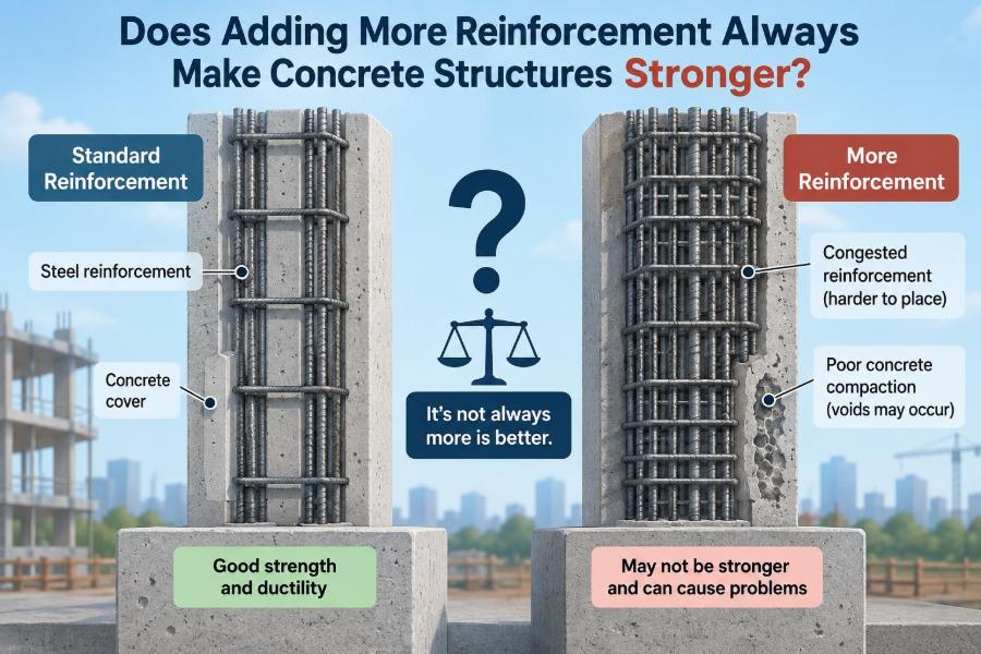

A contractor sees a beam with a dense cage of reinforcing steel and feels reassured. More bars must mean more strength, right? On drawings and construction sites alike, that instinct is understandable: steel is strong, concrete is comparatively brittle, and reinforcement is what allows ordinary concrete members to carry tension safely.
But a heavily reinforced concrete member can become difficult to build, difficult to inspect, and unexpectedly vulnerable to brittle failure. At some point, adding bars may deliver little useful capacity, prevent concrete from being properly placed, or change the way the member fails.
This is not an argument for using less reinforcement indiscriminately. It is an argument for using the right reinforcement, in the right amount, in the right location, with enough space for concrete, vibration, development, and inspection.
For students, the question connects material mechanics to real detailing. For working professionals, it is a reminder that structural capacity is never just a bar-counting exercise.
🧱 Reinforced Concrete Is a Composite Material
Concrete performs well in compression but has limited tensile strength. Reinforcing steel is placed where tension is expected, so the two materials act together as a composite system.
In a simply supported beam under gravity loading, the lower region generally goes into tension near midspan. In a cantilever, the top region near the support is often the tension zone. Reinforcement must follow the actual force path, not merely occupy the member.
Steel and concrete work together because their thermal expansion characteristics are sufficiently compatible for normal construction use, and because the bond between deformed bars and hardened concrete transfers force between them.
📐 Strength Depends on More Than Steel Area
Increasing the steel area can increase flexural strength in many cases, but it is only one variable. Member geometry, concrete strength, steel grade, bar placement, loading, confinement, shear demand, and support conditions all affect the result.
A wider or deeper beam may gain capacity more efficiently than a congested increase in reinforcement. Moving tension steel to an effective depth can also change flexural resistance, provided cover, durability, development length, and constructability remain satisfactory.
The governing question is not “How much steel can fit?” It is “What failure mode governs, and what arrangement provides a safe, buildable load path?”
⚖️ The Desired Failure Sequence in Flexure
Well-proportioned reinforced concrete beams are generally detailed so that tension steel yields before the concrete in compression crushes. This is often called an under-reinforced section.
Steel yielding permits noticeable curvature, cracking, and deflection before ultimate failure. Those signs do not make the condition harmless, but they provide deformation capacity and warning that a brittle concrete-controlled failure may not provide.
As more tension reinforcement is added, the neutral axis shifts and the compression zone becomes deeper. Eventually, concrete can reach its crushing strain before the tension steel has yielded sufficiently.
💥 Why Over-Reinforced Sections Are a Concern
An over-reinforced flexural section contains enough tension steel that the concrete compression zone crushes first. Concrete crushing can occur with limited deformation compared with a tension-controlled response.
That behavior is undesirable because it reduces ductility: the ability to deform substantially while retaining useful load-carrying behavior. Ductility matters for redistribution of forces, seismic response, accidental overloads, and the practical ability to recognize distress.
Design standards therefore place limits on reinforcement ratios or otherwise require ductile behavior through strain-based checks. The exact limits depend on the applicable code, material properties, and design situation; they should never be replaced by a rule of thumb from another jurisdiction.
📊 Balanced, Under-Reinforced, and Over-Reinforced Behavior
The “balanced” condition is a theoretical boundary at which tension steel reaches yield at about the same time that concrete reaches its assumed ultimate compression strain. It is useful for understanding behavior, but designers generally seek a margin on the ductile side rather than treating balance as a target.
| Section behavior | Typical governing event | General implication |
|---|---|---|
| Under-reinforced | Tension steel yields before concrete crushing | Greater deformation capacity and visible distress before ultimate failure |
| Near balanced | Steel yielding and concrete crushing occur close together | Limited ductility margin; requires careful code-based assessment |
| Over-reinforced | Concrete compression zone crushes first | More brittle response; normally avoided in ordinary flexural design |
This comparison applies primarily to flexure. A member can be satisfactory in flexure yet controlled by shear, punching, anchorage, compression, or another limit state.
📏 Reinforcement Ratio Is More Informative Than Bar Count
Four bars are not inherently “more reinforced” than three bars. Bar diameter, member width, effective depth, and bar position determine the reinforcement ratio and the section’s response.
Two beams with the same steel area can also behave differently if one places the bars closer to the tension face within permitted cover limits. The latter may have a larger lever arm between compression and tension resultants.
That is why structural drawings specify bar sizes, quantities, spacing, cover, layers, hooks, and locations. “Add one more bar” is not a harmless field adjustment.
🔩 Bond Is What Lets Steel Carry Tension
A bar develops force through bond with surrounding concrete. Deformations on reinforcing bars, concrete bearing between ribs, friction, and confinement all contribute to the transfer of force over a length.
If a bar terminates too soon, lacks adequate embedment, or is placed in poor-quality concrete, it may slip before reaching its intended stress. Adding more short or poorly developed bars does not solve the underlying anchorage problem.
Development length, lap splices, hooks, headed bars, and mechanical couplers must be designed and detailed for the bar force, concrete condition, confinement, and applicable standard requirements.
🪝 Anchorage Cannot Be Replaced by Extra Bars
Consider a hypothetical cantilever balcony. Its top reinforcement near the support resists the negative bending moment, but only if those bars are anchored adequately into the supporting region.
Placing additional top bars that stop near the support face may create a false sense of security. The critical question is whether the tensile force can be transferred safely into the support through the required development mechanism.
At discontinuities, supports, beam-column joints, and footing connections, anchorage detailing is often as important as the nominal flexural calculation.
🧩 Concrete Needs Room to Flow Around Reinforcement
Fresh concrete is not a liquid that can pass through any opening. Aggregate particles must move between bars and ties, grout must reach around steel, and entrapped air must be removed by appropriate placing and consolidation.
When reinforcement is too congested, concrete may bridge across a cage instead of filling it. The resulting voids, rock pockets, or honeycombing reduce effective section quality and may expose reinforcement to environmental attack.
A theoretically stronger reinforcement layout can therefore produce a weaker built member if it prevents proper concrete placement.
🚧 Congestion Is a Structural Design Problem
Congestion is especially common where demands overlap: beam-column joints, deep transfer beams, pile caps, heavily loaded walls, corbels, anchorage zones, and seismic boundary regions. Longitudinal bars, transverse reinforcement, splices, ducts, embeds, and starter bars may all compete for the same space.
It should not be left entirely to site improvisation. Designers need to consider bar layering, aggregate size, placement direction, splice locations, fabrication tolerances, and the sequence in which concrete can actually be placed.
Constructability reviews and three-dimensional reinforcement coordination can reveal conflicts before steel arrives on site.
🪨 Aggregate Size Affects Detailing Feasibility
Maximum aggregate size influences the clear spacing needed between bars. A spacing that looks generous on a drawing may be inadequate for the selected concrete mix or for the real tolerances of bundled bars and ties.
Reducing aggregate size or using a more flowable concrete mixture can help in some congested regions, but it is not an automatic cure. Mixture changes affect shrinkage, heat development, finishing, pumping, and quality-control requirements.
The best solution is often coordinated: rationalize bar arrangements, avoid unnecessary laps in the same zone, and select a concrete mixture compatible with the detail.
🧰 Bar Spacing Serves Several Purposes
Clear spacing is not merely a drafting convention. It allows concrete placement, helps bond develop around individual bars, enables inspection, and reduces the likelihood that adjacent bars behave like an unmanageable solid bundle.
Cover is different from spacing. Cover protects reinforcement from corrosion, fire exposure, and bond-related problems at the concrete surface; clear spacing governs the open distance between adjacent bars.
Both must be checked in every layer, including locations where bars shift, lap, hook, or cross each other.
🧱 Multiple Layers Can Reduce Effective Depth
When a beam needs more steel, placing bars in a second or third layer is common. But bars farther from the tension face sit closer to the neutral axis and therefore have a smaller lever arm.
Simply adding the areas of all bars without accounting for their centroid can overestimate the benefit. The effective depth should be based on the actual centroid of the tension reinforcement group.
Layering also increases congestion and can complicate stirrup placement. Sometimes a wider member, a deeper member, a different bar diameter, or a revised framing scheme is the cleaner solution.
🛡️ Shear Reinforcement Has a Different Job
Longitudinal bars mainly address flexural tension, while stirrups, links, or other transverse reinforcement are commonly used to resist shear and to confine longitudinal bars. More bottom flexural steel does not automatically provide adequate shear capacity.
Shear failures can be sudden because inclined cracking and aggregate interlock mechanisms change rapidly near ultimate conditions. Design must check shear independently, including the contribution of concrete and properly anchored transverse reinforcement under the relevant code model.
Increasing longitudinal reinforcement may affect certain shear mechanisms, but it is not a substitute for a complete shear design.
🔗 Stirrups Also Restrain and Confine
In beams, closed stirrups help hold longitudinal bars in their intended position during construction. In columns and seismic regions, transverse reinforcement can also confine the core concrete and restrain longitudinal bars against buckling after cracking and large deformation.
Adding longitudinal bars without suitable ties can make this restraint problem worse. Closely spaced bars need appropriate lateral support, particularly where compression reversals or cyclic demands are possible.
The steel cage is a system. Each type of reinforcement affects the performance and constructability of the others.
🏢 Columns Do Not Simply Get Stronger With More Bars
Columns carry combinations of axial compression, bending about one or two axes, shear, and sometimes torsion. Longitudinal reinforcement can increase axial and flexural resistance, but excessive steel can lead to congestion and poor concrete consolidation within the core.
Under sustained compression, concrete cracking, creep, and restraint details also influence how forces are shared between concrete and steel. Column behavior cannot be inferred from a single percentage of reinforcement alone.
Code limits on longitudinal reinforcement and tie or spiral detailing exist partly to preserve constructability and ductile behavior. They are not invitations to fill the section to the maximum amount permitted.
🌀 Confinement Changes Compression Behavior
Concrete under compression expands laterally. Properly detailed transverse reinforcement resists part of that expansion, confining the core and improving its ability to sustain compressive strains.
This effect is especially valuable in regions expected to undergo inelastic deformation, such as some seismic column ends or wall boundary zones. The arrangement, spacing, anchorage, and shape of transverse reinforcement matter; loosely placed ties do not create the same confinement.
More longitudinal steel without compatible confinement may increase demand on the surrounding concrete rather than delivering the desired ductile response.
🌐 Seismic Detailing Prioritizes Ductility
Earthquake-resistant design often accepts that selected regions may yield during severe shaking while the overall structure remains stable. This strategy depends on predictable plastic hinge behavior, confinement, shear strength, and secure anchorage.
Over-reinforcing a beam region can shift damage into a column, joint, or other less ductile location. The objective is not maximum local steel content; it is a controlled hierarchy of strength and deformation across the structural system.
Seismic requirements vary substantially by location, structural system, and governing code. Detailing intended for ordinary gravity loading should not be assumed adequate where significant cyclic demands govern.
🕳️ Punching Shear Around Slabs and Columns
A flat slab can fail in punching shear around a concentrated support if a critical region of concrete breaks out in a truncated-pyramid-like pattern. Adding conventional flexural bars through the slab may not adequately address that mechanism.
Depending on the design, the solution may involve increasing slab depth, enlarging the support region, adding a drop panel or capital, using specifically designed punching shear reinforcement, or revising the column layout.
This is a useful reminder that reinforcement must be matched to the failure mode. Steel in the wrong orientation or location may contribute little where it is needed most.
🌀 Torsion Requires a Closed Load Path
Torsion produces diagonal cracking and circulating shear flow around a member. Reinforcement for significant torsion commonly includes closed transverse reinforcement and longitudinal bars arranged to form a compatible spatial system.
Adding only more bottom bars to a torsion-critical edge beam does not create that closed path. Nor does adding random bars near corners without checking anchorage and interaction with shear and flexure.
Complex force states reward clear load-path thinking: identify the force, identify how it travels, then provide reinforcement that can carry it to the supports.
🌡️ Cracking Is Not Solved by Unlimited Steel
Reinforcement limits crack widths by distributing tensile strain across multiple cracks, but cracking also depends on restraint, shrinkage, temperature change, cover, bar spacing, member thickness, and loading history.
Adding bars can improve crack control when they are appropriately distributed. Yet excessive bar congestion may impair concrete quality, while heavily restrained members may still crack if thermal and shrinkage movements are not accommodated.
For slabs-on-ground, walls, bridge decks, and long continuous elements, joints, sequencing, curing, and movement details can be as consequential as reinforcement quantity.
💧 Durability Begins With Sound Concrete
Durability relies on adequate cover, dense and well-cured concrete, crack control appropriate to the exposure, drainage, and protection against aggressive environments. More reinforcement can be counterproductive if congestion creates voids or makes cover difficult to maintain.
Closely packed bars also create many interfaces where poor consolidation can leave pathways for water and contaminants. Once corrosion begins, expanding corrosion products can crack and spall the surrounding concrete.
In aggressive exposure conditions, material selection and detailing should be coordinated with a durability strategy rather than treated as afterthoughts.
🔥 Fire Resistance Needs More Than Added Bars
Concrete cover helps delay heating of reinforcing steel during a fire. Bar quantity does not eliminate the need for adequate cover, member dimensions, and fire-resistance design appropriate to the building’s requirements.
Congested steel near a surface can make correct cover harder to achieve and verify. If bars are displaced during placement, the as-built condition may differ materially from the drawing.
Fire design should be integrated with strength and durability detailing, especially for slender members or highly loaded columns.
🧪 Material Strength Does Not Cancel Detailing Rules
Higher-strength concrete or higher-strength reinforcing steel can change calculated capacities, but neither material upgrade automatically permits indiscriminate reinforcement increases. High-strength concrete may have different brittleness, bond, confinement, and cracking characteristics than conventional-strength concrete.
Likewise, a higher steel yield strength changes the force that must be developed and the strain relationship at ultimate conditions. Design provisions address these interactions because a simple “stronger material equals more bars allowed” assumption can be unsafe.
Use material properties recognized by the governing design standard and verify the associated detailing provisions.
🧮 Capacity Must Be Checked at Every Limit State
A proper design reviews more than nominal bending resistance. Relevant checks may include flexure, shear, axial load and interaction, torsion, punching, bond, development, splice capacity, service deflection, cracking, vibration, fatigue, stability, and durability.
The governing limit state can change as reinforcement is added. Increasing flexural capacity may expose shear as the next controlling weakness, or move demand into a joint, foundation, connection, or adjacent member.
Structural design is therefore iterative. A local improvement is only useful when the entire load path remains coherent.
🧾 Construction Tolerances Change the Real Arrangement
Design drawings show idealized bar locations, but construction involves tolerances, bar supports, congestion, formwork movement, embedded services, and workers needing access. Small shifts can reduce cover or clear spacing in a crowded cage.
Reinforcement must be supported so it remains in position during concrete placement. A bar that is stepped on, displaced by a pump hose, or pulled aside to fit an embed is not necessarily contributing as assumed in the design.
Clear, coordinated details and inspection hold points are more reliable than hoping a dense arrangement will remain perfect in the field.
👷 Field Changes Need Engineering Review
Common site requests include substituting larger bars, adding bars around an opening, moving a splice, cutting a bar for a pipe, or shifting reinforcement to accommodate an embed. Each can alter force flow, development, cover, and constructability.
Some changes may be acceptable; others may invalidate a critical detail. The safe response is to route the issue to the responsible design professional under the project’s established process.
Unauthorized “extra reinforcement” can be as problematic as omitted reinforcement when it blocks concrete, interferes with other bars, or creates an unverified load path.
🧠 Better Ways to Increase Capacity
When a member genuinely needs more capacity, the best response is often broader than adding bars. The right option depends on the governing failure mode, available geometry, construction stage, and existing conditions.
- Increase member depth or width to improve stiffness, compression capacity, or lever arm.
- Use a different framing layout to shorten spans or redirect loads.
- Increase concrete strength only after checking associated detailing and serviceability effects.
- Add specifically designed shear, punching, torsion, or confinement reinforcement where that mechanism governs.
- Revise openings, supports, or load locations to reduce demand.
- For existing structures, consider engineered strengthening systems after investigation of the actual condition.
Each option has trade-offs. A deeper beam may affect headroom; a larger column may affect architecture; a stronger concrete mix may affect placement. Good design weighs the whole project, not a single calculation output.
🔍 A Practical Review Before Adding Reinforcement
Before increasing reinforcement, work through a disciplined set of questions:
- What load combination and limit state currently govern?
- Is the added steel aligned with the tension, shear, or confinement demand?
- Will the section remain ductile under the applicable design method?
- Are development length, hooks, splices, and bar cutoffs still adequate?
- Can concrete and aggregate pass through the revised cage and be consolidated?
- Are cover, clear spacing, transverse reinforcement, and inspection access maintained?
- Does the change shift demand to supports, joints, foundations, or adjacent members?
This review turns a casual modification into an engineering decision.
⚠️ Common Misconceptions to Leave Behind
“Steel is always stronger than concrete, so more is always safer.” Steel is strong, but the surrounding concrete, bond, anchorage, and failure sequence determine whether that strength can be used safely.
“If it fits in the form, it can be detailed.” A cage must also permit placement, consolidation, cover control, and inspection.
“Extra bars compensate for a missing stirrup.” Longitudinal and transverse reinforcement serve different structural functions.
“The maximum permitted ratio is the best design.” Code limits define boundaries, not an automatic optimum for economy, construction, durability, or ductility.
✅ The Core Principle: Reinforcement Must Be Balanced
More reinforcement can strengthen a concrete structure when it addresses the governing action and remains compatible with ductility, anchorage, concrete placement, and every relevant limit state. In many ordinary flexural members, increasing properly placed tension steel raises capacity up to the point at which other constraints control.
Beyond that point, added steel may have diminishing benefit or create a worse outcome: brittle compression failure, shear-controlled behavior, bond problems, poor consolidation, inadequate cover, or a cage that cannot be built as designed.
The strongest concrete structure is not the one with the most steel. It is the one with a clear load path, proportionate members, correctly detailed reinforcement, sound materials, and quality construction.
Adding reinforcement makes concrete structures stronger only when the entire structural system can safely and constructively use it. That is the engineering judgment behind every well-detailed bar on a drawing. 🏗️🧱