
A newly cast concrete floor can look perfectly level when the formwork is removed. Months or years later, the same floor may appear slightly lower at midspan, partitions may crack, or a ceiling line may no longer look quite straight.
Nothing dramatic may have happened. The furniture has not changed, the beam has not visibly cracked, and there has been no obvious overload. Yet the deflection has increased.
This is one of concrete’s most consequential time-dependent behaviors. It affects serviceability—the everyday performance of a structure—not just whether a member has enough strength to avoid collapse.
Understanding why it happens helps designers choose sensible member sizes and reinforcement, and helps site teams and building owners distinguish expected long-term movement from a condition that deserves investigation.
🏗️ The short answer: concrete keeps deforming
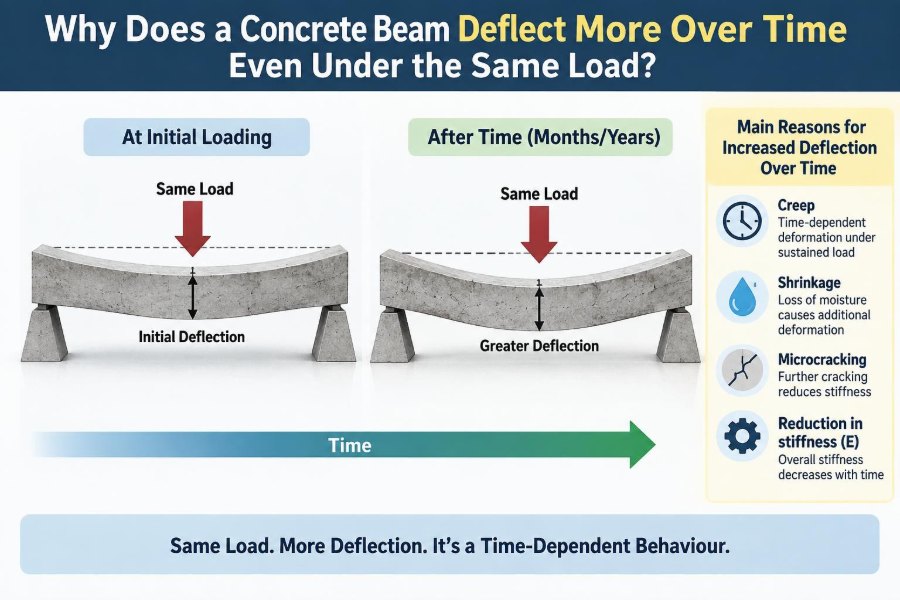
A beam deflects immediately when load is applied because its material strains elastically. Concrete, however, also undergoes time-dependent strain: it continues to change shape under sustained stress.
The main contributors are creep and shrinkage. Creep is extra strain that develops while concrete remains loaded. Shrinkage is contraction caused mainly by moisture leaving the concrete, even when external load is unchanged.
In a reinforced concrete beam, these effects interact with cracking, reinforcement, and support restraint. The result is commonly called long-term deflection.
📏 What engineers mean by deflection
Deflection is the displacement of a structural member from its intended position. For a simply supported beam carrying downward gravity load, the largest vertical deflection is often near midspan.
Deflection is different from strength. A beam can safely resist its design bending moment and shear while still deflecting enough to crack finishes, pond water on a roof, interfere with doors, or look unacceptable.
Design therefore checks both ultimate limit states, related to safety, and serviceability limit states, related to usable performance, comfort, appearance, and durability.
⚡ The immediate elastic response
When a load is first placed on an uncracked beam, its initial curvature is governed by bending stiffness, often represented by EI. Here, E is the elastic modulus of the material and I is the second moment of area of the section.
A larger EI means a stiffer beam and less initial deflection. This first movement is not usually the whole story for concrete because neither E nor the section’s effective stiffness remains simple and constant throughout its life.
A useful mental picture is a ruler: push it and it bends immediately. Concrete responds that way too, but under a sustained load it then undergoes a slow additional deformation.
⏳ Creep: strain under sustained stress
Creep is the gradual increase in concrete strain under a maintained stress. In a beam, sustained bending stress produces additional compression strain in the compression zone, increasing curvature and therefore downward deflection.
Creep is most pronounced while concrete is relatively young and moisture can move through its internal pore structure. It develops rapidly at first and then more slowly, but its effects can continue for a long period.
Creep is not a sign that the beam is “giving up.” It is an inherent material behavior that structural design methods explicitly account for.
🧱 What happens inside creeping concrete
Hardened cement paste contains pores and adsorbed water at microscopic scales. Under sustained stress, moisture redistribution and gradual internal rearrangement allow incremental strain beyond the original elastic response.
The detailed mechanisms are complex and depend on moisture condition, paste characteristics, aggregate restraint, stress level, and age. For practical design, the key point is that concrete is not perfectly elastic over time.
Aggregate matters because it acts as a relatively stiff skeleton within the paste. Stiffer, well-graded aggregate can restrain paste deformation more effectively than a concrete with a more deformable aggregate system.
💧 Shrinkage: movement without extra load
Shrinkage is a reduction in concrete volume, mainly associated with drying. It can occur without any increase in applied structural load, which is why it must not be confused with creep.
In a plain, freely supported concrete prism, uniform shrinkage would mainly shorten the member. In a reinforced beam, steel restrains part of that shortening. That restraint creates internal stresses and can contribute to curvature.
Drying is rarely uniform through a member. Surfaces exposed to air tend to dry sooner than the interior, especially in thin slabs and beams with a large exposed surface area.
🌡️ Shrinkage is not only drying shrinkage
Several volume-change mechanisms can be relevant. Drying shrinkage is often the dominant long-term concern in ordinary exposed structural concrete, but early-age effects also matter.
- Autogenous shrinkage occurs as hydration consumes water within the cement paste and can be more significant in low-water, high-strength mixtures.
- Plastic shrinkage can occur before concrete sets if surface evaporation is rapid.
- Thermal contraction follows cooling after heat generated by cement hydration, particularly in larger placements.
These mechanisms have different timing and causes, but early cracking or restraint effects can influence the beam’s eventual serviceability behavior.
↪️ Why shrinkage can make a beam sag
Reinforcement is commonly placed near the tension face of a gravity-loaded beam. When concrete wants to shrink, the steel restrains it locally. Because the reinforcement is not usually centered in the section, that restraint can create curvature.
For a typical simply supported beam with bottom reinforcement, free shrinkage restrained by that eccentric steel tends to produce curvature that can add to downward sag. The exact effect depends on reinforcement layout, cracking, member geometry, and restraint conditions.
This is why a beam can develop more deflection even if the sustained external load remains unchanged.
🪨 The role of aggregate and mix proportions
Concrete is not one material with one fixed creep or shrinkage value. Its behavior depends strongly on the mixture. The cement paste is generally more prone to time-dependent deformation than the aggregate.
A high paste content, excessive mixing water, or aggregate with lower stiffness can increase susceptibility to shrinkage and creep. Conversely, a well-proportioned mix with suitable, stiff aggregate generally has better dimensional stability.
That does not mean a designer should prescribe a mix solely to minimize shrinkage. Workability, strength, durability, pumping, finishability, heat generation, and local material availability also have to be balanced.
🌬️ Humidity and member size change the outcome
Concrete exposed to a dry environment loses moisture more readily, so shrinkage tends to be greater. Higher ambient relative humidity generally reduces drying shrinkage, although it does not eliminate creep.
Member size matters because drying occurs through exposed surfaces. A thin slab or narrow beam can dry through much of its depth relatively quickly, while the core of a massive member may remain moist for much longer.
Engineers often describe this through a notional size related to cross-sectional area and exposed perimeter. More exposed surface relative to volume generally means faster and greater drying-related effects.
🕰️ Loading age matters
Concrete loaded at an early age generally creeps more than concrete loaded later. At early ages, hydration and microstructural development are still progressing, so the material is more sensitive to sustained stress.
This matters in construction sequencing. Removing shores, applying construction loads, stressing a member, or placing upper floors onto a young frame can all affect the starting point for long-term deformation.
The implication is not that early loading is always unacceptable. It means the actual sequence should be recognized in design assumptions and construction planning.
🌿 Curing changes the starting conditions
Good curing helps concrete hydrate and limits early moisture loss. This improves near-surface quality and can reduce the tendency for early shrinkage cracking.
Poor curing does not simply create a cosmetic problem. Rapid early drying can increase shrinkage gradients and leave the member with a less favorable condition for serviceability.
Curing cannot make long-term deformation disappear, but it is a practical way to avoid making it worse. The most useful curing method and duration depend on the mixture, climate, element type, and project requirements.
🪢 Reinforcement restrains, but does not freeze, movement
Steel reinforcement is much stiffer than concrete in tension and plays a central role after cracking. It limits crack width and provides tensile resistance, but it cannot prevent all long-term curvature.
Increasing tension reinforcement can reduce long-term deflection by reducing steel stress and by improving the cracked section’s stiffness. Yet simply adding bars is not an unlimited remedy: congestion, constructability, anchorage, cost, and code limits still apply.
Compression reinforcement can be particularly helpful for long-term behavior because it participates in resisting creep-related strain in the compression region and improves the section’s time-dependent stiffness.
🩹 Cracking changes the beam’s effective stiffness
Concrete is weak in tension compared with compression. Once bending tension exceeds the concrete’s tensile capacity, cracks form in the tensile zone. This is expected in many reinforced concrete beams under service loads.
After cracking, the beam no longer behaves like a fully uncracked concrete section. The reinforcement carries most of the tension across cracks, and the effective bending stiffness decreases.
Between cracks, concrete still contributes through tension stiffening, so the behavior lies between fully gross-section and fully cracked-section assumptions. This is why deflection calculations use an effective stiffness, not a single simplistic value.
🔄 Creep and cracking reinforce each other
Long-term deflection is rarely just “initial deflection multiplied by a creep factor.” Sustained load causes creep, creep increases curvature, and cracking changes stiffness. As stiffness changes, the same load can produce more curvature.
Shrinkage can also widen existing cracks or encourage additional cracking where tensile restraint is present. Wider cracks alter the tension-zone contribution and can further reduce effective stiffness.
Design provisions use simplified models to capture this coupled behavior. They are approximations, but they are based on the recognition that a cracked reinforced concrete beam changes over time.
🏠 Sustained load is the load that keeps working
Not all loads are present long enough to cause the same creep response. The self-weight of the beam and slab is sustained for the structure’s life. Permanent finishes, fixed partitions, façade loads, and permanently installed equipment may also be sustained.
Occupancy live load is different. Some portion may be sustained in a particular building, but a full design live load is not necessarily present continuously.
For long-term deflection, separating permanent and realistically sustained loads from short-duration loads is essential. A beam’s loading history matters as much as the final load diagram.
📐 Span depth is often the first deflection lever
Beam deflection is highly sensitive to span and depth. For a given loading arrangement, deflection increases rapidly as span increases, while increasing depth substantially raises the second moment of area.
That is why a modest increase in beam depth can be more effective than small adjustments to concrete strength. A deeper member is not always architecturally possible, but it is frequently the most direct stiffness solution.
Long spans, shallow floor zones, and open-plan spaces are therefore serviceability-sensitive even when strength calculations appear comfortable.
📊 A practical comparison of common influences
| Factor | Typical influence on long-term deflection | Design or construction response |
|---|---|---|
| High sustained stress | More creep-related curvature | Improve section stiffness or revise load path |
| Young loading age | Greater creep potential | Plan shoring and construction sequence |
| Dry exposure | More drying shrinkage | Specify suitable curing and account for environment |
| Cracked tension zone | Lower effective stiffness | Check cracked-section deflection and reinforcement layout |
| Long span or shallow depth | Large curvature becomes visible displacement | Increase depth, add supports, or change framing |
| Higher reinforcement ratio | Usually improves stiffness, within limits | Optimize rather than add steel indiscriminately |
🔢 How design methods estimate long-term deflection
Design standards provide procedures for estimating immediate and long-term deflection. Details differ by jurisdiction and code edition, so a project should use the governing standard and its stated assumptions.
Common approaches start with an immediate deflection based on effective moment of inertia or cracked-section analysis. They then apply a time-dependent multiplier or calculate added curvature from creep and shrinkage.
More refined analysis may consider staged loading, age at loading, humidity, member size, concrete properties, reinforcement ratios, cracking, and support conditions. Refinement is most worthwhile where deflection is critical or geometry is unusual.
🧮 A simple conceptual beam example
Imagine two identical simply supported reinforced concrete beams carrying the same permanent load. Beam A is loaded soon after construction and exposed to a dry interior environment. Beam B is loaded later after a longer curing period and remains in a relatively humid environment.
Both beams deflect immediately. Over time, Beam A would generally be expected to develop more additional deflection because its concrete was younger at loading and is more prone to drying-related strain in the stated hypothetical conditions.
The example does not predict a numerical value; real behavior also depends on mix design, aggregate, cracking, reinforcement, and actual restraint. It illustrates why “same load” does not mean “same lifetime deflection.”
🏢 Slabs and continuous beams behave differently
A one-way simply supported beam is useful for learning, but real buildings often use continuous beams, slabs, flat plates, and frames. Continuity creates negative moments over supports and redistributes curvature across the system.
Long-term effects can alter moment distribution because cracked regions and creep-relieved regions do not all have the same stiffness. Support settlement, restraint from walls, and interaction with nonstructural elements can add further complexity.
For slabs, two-way action, punching regions, openings, and column-strip stiffness may govern the deflection pattern. A simplified beam analogy should not replace system-level analysis where the structure requires it.
🏗️ Construction sequence can create hidden deflection
Multi-storey concrete construction often involves shores and reshores. As new slabs are cast, lower floors may temporarily carry construction loads before the concrete reaches its intended strength and stiffness.
If this sequence is ignored, calculated long-term deflection may not represent what the building actually experienced. The distribution of temporary loads through several floors can matter greatly.
Construction planning should therefore align with the structural engineer’s assumptions. Changes to stripping times, reshoring practice, or material loading areas should not be treated as purely site logistics.
🧭 Camber is a controlled geometric allowance
Camber is an intentional upward curvature introduced so that a member approaches the desired level after dead-load and long-term deflection occur. It is common in some precast and prestressed elements and may be considered in selected cast-in-place systems.
Camber is not a substitute for adequate stiffness. Its prediction has uncertainty because actual creep, shrinkage, loading time, and construction tolerances vary.
It must also be coordinated with adjacent construction. A member that remains too high can create drainage, floor-finish, or connection problems just as a member that sags too much can.
⚙️ Prestressing changes the deflection story
Prestressed concrete introduces compressive force before service loading. This can reduce tensile cracking and may create upward camber that offsets gravity-load deflection.
However, prestress losses occur over time due to concrete creep and shrinkage, steel relaxation, and other factors. Long-term deflection analysis for prestressed members must account for these losses as well as the applied loads.
Prestressing can be an excellent solution for longer spans, but it requires specialized detailing, construction control, and careful prediction of time-dependent behavior.
🚧 Signs that merit engineering review
Some long-term deflection is anticipated, especially in slender reinforced concrete members. Observation alone does not establish whether a condition is safe or unacceptable.
Review is prudent when deflection is accompanied by unusual cracking, water ponding, jammed doors or windows, damaged finishes, unexpected vibration, change after a new load was added, or visible distress near supports.
Measurements should be interpreted carefully. A level survey or monitoring record is more informative than a single visual impression, and an engineer needs the member geometry, loading history, reinforcement details, and support conditions to assess the cause.
❌ Common misconceptions about sagging beams
- “More strength means less deflection.” Higher compressive strength may improve stiffness somewhat, but geometry, cracking, creep, and reinforcement often dominate.
- “A beam that does not crack will never sag more.” Uncracked concrete can still creep and shrink.
- “All live load acts forever.” Long-term calculations should reflect sustained loading, not automatically the full transient load.
- “Extra steel always solves it.” Reinforcement helps, but span, depth, construction sequence, and load arrangement may remain controlling.
- “Deflection proves inadequate strength.” Serviceability and strength are related but distinct checks.
🧰 Design choices that reduce long-term deflection
The most effective strategy is usually to address serviceability early, when framing geometry is still flexible. Trying to correct a too-slender member after architectural coordination is complete is much harder.
- Increase member depth or revise the span arrangement.
- Use a reinforcement layout that supports cracked-section and long-term performance.
- Identify sustained loads realistically, including finishes and fixed equipment.
- Specify concrete appropriate for the exposure, strength, durability, and dimensional-stability needs.
- Consider compression reinforcement, continuity, drop panels, prestressing, or intermediate supports where appropriate.
- Coordinate expected deflection and camber with finishes, partitions, drainage, and façades.
🧪 Material specifications need realistic expectations
Specifying a higher concrete strength alone is not a universal deflection-control measure. The relationship between compressive strength, elastic modulus, shrinkage, and creep depends on the materials and mix proportions used.
Where long-term movement is critical, the project team may need to discuss aggregate source, modulus assumptions, shrinkage performance, curing requirements, and trial data where available. Such discussion is especially valuable for long-span floors and sensitive finishes.
Any performance requirement should be measurable, relevant to the project exposure, and coordinated with the concrete supplier and contractor. Unrealistic limits can create disputes without improving the finished structure.
🛠️ Repair decisions require diagnosis first
If excessive deflection is suspected, the first question is not “How do we push it back up?” It is whether movement is ongoing, whether loads changed, and whether the member has adequate capacity and support conditions.
Possible interventions range from load reduction and finish repairs to added supports, externally bonded reinforcement, section enlargement, or replacement. Each has different effects on strength, stiffness, durability, fire resistance, and building operations.
Jacking a beam without a designed repair scheme can crack finishes, transfer force unexpectedly, or create new problems at connections. Evaluation and repair design should be performed by a qualified structural engineer.
🧠 A useful way to think about time-dependent behavior
Concrete beam deflection is best understood as a history, not a single event. The final shape reflects when the member was loaded, how long loads remained, whether it cracked, how it dried, how it was cured, and how its steel and supports restrained movement.
This perspective explains why two beams with the same dimensions and final load can behave differently. Their material condition and load history may not be the same.
For students, this is the bridge between textbook elastic analysis and real structural performance. For practicing engineers, it is a reminder to connect calculations with detailing, sequencing, and site conditions.
✅ The core takeaway for durable, usable floors
A concrete beam deflects more over time under the same load chiefly because sustained stress causes creep and moisture-related volume change causes shrinkage. Cracking and the resulting reduction in effective stiffness often amplify the visible effect.
Good serviceability design does not attempt to eliminate all movement. It anticipates realistic time-dependent behavior, provides sufficient stiffness and reinforcement, accounts for loads and construction sequence, and protects the performance of the systems attached to the structure.
Concrete does not stop responding when the load stops changing; its internal strain, stiffness, and curvature continue to evolve with time.
When long-term deflection is treated as a predictable design condition rather than a surprise, concrete structures can remain level-looking, functional, and durable throughout their service life. 🏗️📐⏳