
A warehouse owner wants to install heavier storage racks. A school plans to convert an unused roof into a terrace. An office building is being adapted for archives, new mechanical equipment, or a different occupancy. These projects may appear straightforward until someone asks a deceptively simple question: can the existing structure carry the new load?
Buildings are not empty containers. Their slabs, beams, columns, walls, foundations, and connections form a continuous load path, each part designed for particular actions and limits. Adding capacity to one visible member does not automatically make the whole system stronger.
Increasing load-carrying capacity can be an excellent alternative to demolition and replacement. It can extend a structure’s useful life, support adaptive reuse, and reduce disruption. But it is also a safety-critical engineering task that begins with evidence, not a strengthening product catalogue.
The central challenge is to identify what limits the structure, determine how new loads travel to the ground, and select an intervention that improves the governing weakness without creating another one.
🧱 Start With the Meaning of Capacity
Load-carrying capacity is the ability of a structural system to resist applied actions without unacceptable failure, instability, damage, or deformation. Capacity is not only a question of whether a member breaks; excessive deflection, cracking, vibration, or connection slip can make a structure unsuitable well before collapse.
A floor may be strong enough in bending but too flexible for sensitive equipment. A column may resist vertical load but lack sufficient fire protection or seismic confinement. Engineers therefore evaluate capacity against the intended performance requirements, not a single strength value.
📦 Identify What Load Is Actually Increasing
The proposed use determines the assessment. Permanent loads include the self-weight of construction, finishes, fixed partitions, and permanently installed equipment. Variable loads include people, furniture, movable storage, vehicles, snow, and maintenance activity.
A change in use often changes both the magnitude and distribution of loading. For example, library shelving produces concentrated lines of load, while a public gathering space produces broadly distributed live load and may introduce vibration concerns.
- New plant equipment can create concentrated loads and dynamic forces.
- Raised floors add permanent load across a large area.
- Storage racks may transmit high point loads through small base plates.
- Roof-mounted equipment can introduce wind-related uplift as well as gravity load.
🧭 Trace the Complete Load Path
Every added force needs a continuous route to the ground. A roof unit loads its support frame, then roof members, beams or walls, columns, foundations, and supporting soil. This route is called the load path.
Strengthening a slab beneath a machine may be ineffective if the supporting beam, column, connection, or footing becomes the weak link. Load-path thinking also reveals where a proposed transfer beam will send new reactions and whether those reactions can be safely received.
📐 Define the Required Performance Level
The question is not merely “how much more weight?” A sound brief defines the new use, load arrangement, duration, environmental exposure, required service life, and relevant design actions such as wind, seismic effects, temperature movement, or accidental impact.
The acceptable level of movement matters too. An industrial floor serving a forklift may tolerate behavior that would be unacceptable for brittle finishes, masonry partitions, or precision laboratory equipment. Clear performance targets prevent both under-design and unnecessarily invasive work.
🗂️ Collect Drawings, Records, and Change History
Original drawings, calculations, specifications, inspection reports, alteration records, and maintenance histories are valuable starting points. They can indicate member sizes, reinforcement layouts, steel grades, foundation assumptions, and past repairs.
However, documents are evidence rather than proof. Buildings are sometimes altered during construction, and later renovations can introduce openings, remove walls, add services, or change load paths. A field survey is needed to reconcile records with reality.
🔍 Survey the Structure Before Designing a Fix
A detailed site survey records member dimensions, support conditions, visible damage, deflection, corrosion, moisture ingress, alterations, and accessibility. It should include the areas that receive the added load and the elements below them.
Small details can govern the scheme: a beam flange blocked by services, a hidden opening in a wall, limited headroom for a new support, or inadequate space for construction equipment. Strengthening that cannot be installed safely and inspected properly is not a practical solution.
🧪 Investigate Materials and Hidden Construction
Material properties may be uncertain in older structures or structures with incomplete records. Depending on the system and the assessment question, an engineer may use non-destructive examination, local openings, reinforcement scanning, sampling, or laboratory testing.
Concrete assessment can involve cover measurement, reinforcement location, condition mapping, and carefully planned cores where appropriate. Steelwork may require confirmation of section geometry, corrosion loss, weld details, and connection configuration. Investigation should be proportionate: intrusive work has cost and can itself affect finishes or structural behavior.
🧮 Use Assessment Loads and Combinations Correctly
Structural verification uses combinations of actions rather than simply adding every maximum load together. Design standards establish how permanent, variable, environmental, and accidental actions are considered, including relevant factors and combinations.
The applicable requirements depend on jurisdiction, building type, material, and the nature of the alteration. A qualified structural engineer must apply the current locally adopted rules and determine whether an existing-building assessment permits a different methodology from new construction design.
⚖️ Separate Ultimate Strength From Serviceability
Ultimate limit states concern safety against collapse, rupture, buckling, punching shear, and other failure modes. Serviceability limit states concern behavior in normal use, including deflection, vibration, crack width, settlement, and water tightness.
A retrofit can pass a strength check yet remain inadequate in service. For instance, a slender floor may safely support additional office load but bounce uncomfortably under walking. Conversely, a stiffening measure may improve comfort without correcting an underlying strength deficiency. Both checks are needed.
🧱 Understand the Common Limits of Concrete Members
Reinforced concrete beams and slabs may be limited by flexure, shear, punching shear near columns, anchorage, cracking, or deflection. Columns may be limited by compression, bending from frame action, slenderness, or deterioration of the concrete and reinforcement.
Concrete capacity depends heavily on detailing and condition. A slab that appears thick may still be governed by insufficient reinforcement at supports, while a heavily loaded column may be controlled by confinement details rather than concrete strength alone.
🔩 Understand the Common Limits of Steel Members
Steel beams can be governed by yielding, lateral-torsional buckling, local buckling, web shear, or excessive deflection. Columns require checks for overall and local buckling, and their effective length depends on real restraint conditions.
Connections deserve equal attention. Bolts, welds, end plates, seat angles, and supporting member webs may control the available capacity. A larger beam attached to an unchanged, weak connection does not deliver the strength shown in a beam-only calculation.
🪵 Respect Timber and Masonry Behavior
Timber strength varies with species, grade, moisture, duration of loading, defects, connection details, and biological condition. Moisture management is particularly important because decay or insect damage can reduce effective section over time.
Masonry is strong in compression but generally weak in tension and sensitive to support movement. Adding loads to a masonry wall requires assessment of wall condition, eccentricity, lateral restraint, bearing zones, and the foundations below. Local crushing at a new beam bearing is a common concern.
🕳️ Check Foundations and the Ground
Additional load eventually reaches the soil or rock. Existing footings may be limited by bearing resistance, settlement, sliding, overturning, structural bending, punching, or interaction with neighboring foundations.
Ground behavior is uncertain without suitable information. A shallow footing can have adequate bearing resistance yet experience excessive settlement, particularly where new loads are uneven or groundwater conditions have changed. Foundation investigation and geotechnical input are often essential when column loads increase materially.
📉 Consider Deterioration as a Capacity Problem
Corrosion, rot, cracking, spalling, water penetration, chemical exposure, fire damage, and impact damage can reduce capacity or accelerate future loss. Strengthening over active deterioration is rarely a durable solution.
For example, adding steel plates to a corroding member may conceal the source of moisture while corrosion continues at interfaces. First identify the mechanism, stop or manage it, repair damaged material where necessary, and then evaluate the strengthened system.
🔧 Strengthen by Reducing Demand First
The least intrusive way to increase apparent capacity is often to reduce the load demand. Relocate heavy equipment nearer to supports, spread a point load with a designed grillage, reduce stored quantities, use lighter finishes, or limit access to areas with lower capacity.
These measures are not shortcuts when properly engineered. A hypothetical rooftop air-handling unit might be moved from midspan to a location directly above a load-bearing line, reducing bending in the roof framing while still requiring checks of local bearings and foundations.
➕ Add New Supports or New Load Paths
New columns, walls, braces, hangers, or transfer members can shorten spans and divert load away from overstressed members. This approach can be highly efficient because it changes the structural geometry rather than asking one existing element to do all the work.
Its trade-offs are architectural and foundation-related. A new column may obstruct circulation, require a new footing, and introduce differential settlement risk. Temporary works are also needed because load transfer into the new support must be controlled.
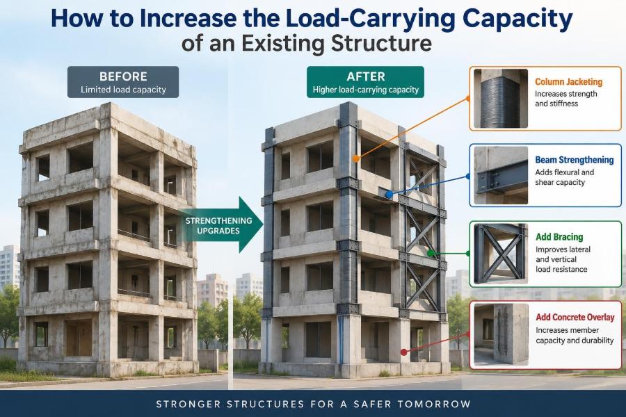
🏗️ Increase Section Size With Jacketing or Plating
Concrete jacketing enlarges an existing member with new reinforced concrete, improving compression, shear, stiffness, or confinement when detailed and connected correctly. Steel plate or section additions can increase steel member capacity, while timber members may be reinforced with sister members or engineered inserts.
Composite action is the key issue. The new material must reliably share force with the existing member through connectors, shear transfer, anchorage, and compatible deformation. Simply placing material beside a member does not guarantee that it carries meaningful load.
🧵 Use Fiber-Reinforced Polymer Carefully
Fiber-reinforced polymer, often called FRP, can be bonded externally to concrete or masonry to improve flexural, shear, or confinement performance. It is thin, lightweight, and useful where access or added dead load must be limited.
Its performance depends on surface preparation, adhesive application, anchorage, substrate condition, detailing around corners, and environmental protection. FRP can be vulnerable to poor bond conditions, impact, ultraviolet exposure, and elevated temperatures unless an appropriate protective system is provided.
🪛 Improve Connections, Bearings, and Local Zones
Capacity upgrades frequently succeed or fail at local details. A steel connection may need additional bolts, stiffeners, welds, or bearing plates. A concrete support may need local thickening, new reinforcement, or a designed shear-transfer detail.
Where a new beam bears on masonry, the wall may need a spreader plate, padstone, or localized reconstruction to prevent crushing. The load from a strengthening scheme is often more concentrated than the original arrangement, so local stress checks are indispensable.
🧷 Address Shear, Punching, and Anchorage Explicitly
Flexural strengthening gets attention because it is visually intuitive, but brittle shear-related failures can govern. Deep beams, short spans, supports, slab-column connections, and heavily loaded openings require particular care.
At a flat slab column, punching shear is the risk of a column pushing through the slab around its perimeter. A thicker topping or stronger beam elsewhere may not resolve it. Similarly, added reinforcement is only useful if it has sufficient development length and anchorage to mobilize its strength.
🌬️ Do Not Ignore Lateral Stability
A project intended to add gravity load can affect lateral behavior. New walls may create torsional irregularity, removed partitions may reduce bracing, and a new rooftop unit can increase wind or seismic demand on the supporting system.
Check diaphragms, frames, shear walls, braces, collectors, connections, and foundations as a coordinated lateral-force-resisting system. Stiffening one part of a building can attract more lateral force to it, changing how loads are distributed.
🔥 Protect the Retrofit in Fire and Durability Exposure
Strengthening must function for the required duration under fire exposure and anticipated environmental conditions. Added steel may need fire protection; adhesive-based systems need temperature considerations; new reinforcement requires adequate cover and corrosion protection.
Durability detailing includes drainage, waterproofing, movement accommodation, compatible repair materials, and access for maintenance. A technically strong repair that traps water or cannot be inspected may have a short useful life.
🚧 Plan Temporary Works and Construction Sequence
Construction can impose loads that do not exist in the completed building. Removing a wall, drilling through a slab, welding near finishes, jacking a beam, or placing wet concrete can temporarily alter stability and loading.
A construction sequence should specify temporary supports, load transfer stages, limits on stored materials, monitoring needs, and the order of connection. Jacking requires special care: excessive lifting can crack finishes, damage brittle elements, or introduce unintended force into adjacent members.
📏 Monitor Behavior During and After the Work
Monitoring may include crack gauges, level surveys, deflection readings, strain measurements, vibration observations, or visual inspections. The aim is not to generate data for its own sake; it is to confirm that behavior remains consistent with expectations and to trigger action if it does not.
Baseline measurements before work are valuable. If a pre-existing crack changes later, the team can distinguish ongoing movement from a condition that was already present. Monitoring is especially useful where load transfer, settlement, or delicate historic fabric creates uncertainty.
📝 Document the Completed Structural System
Keep records of approved calculations, surveys, material certificates, inspection results, photographs of concealed work, as-built dimensions, and maintenance requirements. Future owners and engineers need to know where strengthening exists and what assumptions it relies on.
Documentation also prevents accidental damage during later renovation. Cutting through an unrecorded FRP strip, removing a new brace, or overloading a strengthened bay beyond its intended use can undo the safety margin created by the retrofit.
🚫 Avoid Common Capacity-Increase Mistakes
Several mistakes recur because they focus on a visible component while overlooking system behavior:
- Assuming old drawings describe the building exactly as built.
- Checking only the floor and not beams, columns, connections, or foundations.
- Using a strengthening product without designing its force transfer and anchors.
- Ignoring vibration, deflection, cracking, fire, corrosion, or construction-stage effects.
- Adding a support without checking its footing and the ground beneath it.
- Allowing heavy construction materials to be stored on a floor being assessed.
The remedy is disciplined verification, coordinated design, and site observation—not optimism based on a member’s apparent size.
👷 Know When Specialist Input Is Essential
Any meaningful increase in load, change of occupancy, visible distress, removal of structural elements, or alteration near foundations should be reviewed by a competent structural professional. Projects involving historic fabric, post-tensioned concrete, major corrosion, fire damage, seismic upgrades, or uncertain ground conditions often require additional specialists.
Building-code approvals, permits, inspections, and responsibilities vary by location. This article explains general engineering principles; it is not a substitute for a site-specific assessment, design, and review under applicable local requirements.
🧠 Choose the Intervention That Solves the Governing Problem
There is no universal “best” strengthening method. The right choice balances structural effectiveness, constructability, disruption, durability, fire performance, architectural impact, future adaptability, and cost over the intended service life.
A modest load reduction may outperform an elaborate retrofit. A new support may be more reliable than external reinforcement. In another case, a lightweight FRP system may be preferable because a foundation cannot accept much additional self-weight. Good decisions follow the evidence.
✅ The Core Principle: Strengthen the System, Not Just the Member
Increasing load-carrying capacity is a process of understanding an existing structure before changing it. Define the new demand, verify materials and geometry, trace every load path, check strength and serviceability, and account for foundations, connections, durability, and construction stages.
The most successful retrofit is usually the one that addresses the actual governing limit with the simplest reliable load path. It makes the building safer and more useful without transferring an unresolved problem to the next element in the chain.
Capacity increases are achieved responsibly when the entire structural system—from the applied load to the supporting ground—is assessed and upgraded as one connected whole. 🏗️📐🔍