
From the sidewalk, a high-rise can seem almost weightless: a glass facade, a narrow footprint, and dozens of occupied floors rising above traffic. Yet every chair, elevator, gust of wind, and concrete slab must ultimately be supported by the ground beneath it.
That support is not a single act of strength. It is a carefully planned chain of structural elements, each receiving force, resisting deformation, and passing load onward without creating a weak link.
For students, tracing this chain makes drawings and analysis models far easier to read. For working professionals, it is a useful reminder that changes to one member, opening, connection, or foundation assumption can affect the entire building.
The central question is simple: where does the load go? The answer reveals why high-rise structural engineering is less about making every component massive and more about creating a reliable, continuous path to the ground.
🧭 Start With the Load Path
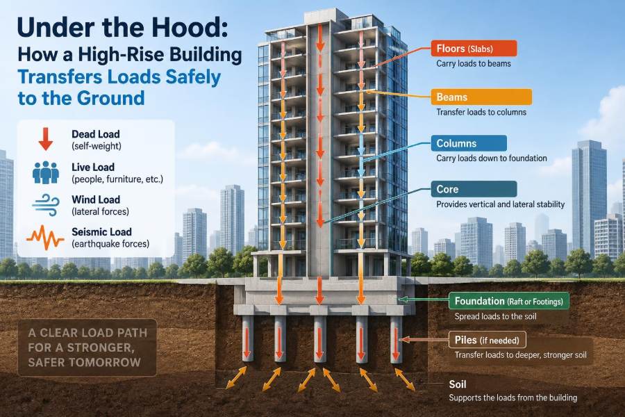
A load path is the route a force follows through a structure to its support. In a typical tower, gravity loads move from floor finishes and occupants into slabs, then into beams or directly into columns and walls, down through the vertical structure, into foundations, and finally into soil or rock.
Engineers do not merely assume this route exists. They identify it explicitly for every major load case. A member can be strong on its own yet still be unsafe if its connection or supporting element cannot transfer the force onward.
📦 What Counts as a Load?
Buildings carry several categories of load, and each produces different demands. Gravity is only one part of the picture.
- Dead load: permanent weight from slabs, beams, walls, facade systems, finishes, and fixed equipment.
- Live load: movable occupancy loads such as people, furniture, stored materials, and some maintenance activity.
- Environmental load: wind, earthquake effects, snow where relevant, temperature movement, and rainwater accumulation.
- Construction load: temporary forces from fresh concrete, cranes, material storage, and partially completed framing.
The governing condition is often a combination rather than one load acting alone. Design standards prescribe combinations and safety factors, but their application depends on the project location, structural system, and applicable code.
⬇️ Gravity Follows a Direct Route
Gravity pulls downward, so its preferred path is intuitive: floor to vertical support to foundation. In reality, the route may shift around atriums, transfer floors, mechanical spaces, and architectural setbacks.
A good gravity system limits unnecessary detours. When loads must turn or concentrate, engineers provide members designed for bending, shear, bearing, and connection forces created by that redirection.
🧱 Floors Are More Than Walking Surfaces
A floor slab is often the first structural element to receive occupancy and finish loads. Reinforced concrete slabs distribute load through bending; composite steel decks and slabs share action between steel and concrete; timber systems use panels, joists, or beams.
How a slab spans matters. A one-way slab mainly carries load in one direction, while a two-way slab distributes it toward supports on multiple sides. Openings for stairs, elevators, and services interrupt this behavior and commonly require local framing or reinforcement.
↔️ Beams Gather and Redirect Load
Beams collect load from slabs, walls, or smaller framing members and transfer it to columns, cores, or major walls. Their fundamental demand is bending: the beam curves under load, placing one region primarily in compression and another in tension.
At beam supports, shear becomes especially significant. A beam sized only for bending can still be inadequate if its web, stirrups, connection, or bearing region cannot safely carry the support reaction.
🧩 Girders Organize Larger Spans
A girder is a primary beam that supports other beams. This hierarchy lets a floor framing plan collect numerous smaller loads into fewer, larger reactions at columns or walls.
The arrangement is similar to a drainage network: small branches feed larger channels. The analogy has limits, but it captures why reactions become larger as the load path approaches the foundation.
🏛️ Columns Carry Compression Downward
Columns are vertical members intended mainly to carry axial compression. In a high-rise, a lower-level column supports not only its own floor but also the accumulated gravity load from many stories above.
That does not mean lower columns are simply made wider. Engineers may use stronger concrete, built-up steel sections, composite steel-and-concrete columns, or a changed column layout. The choice must also account for fire resistance, construction sequence, architectural space, and connection detailing.
🧱 Structural Walls Can Carry Gravity Too
Reinforced concrete walls, particularly core walls around elevators and stairs, often carry substantial gravity load in addition to resisting lateral forces. Their broad area can distribute compression efficiently and provide a convenient vertical route through the building.
Walls require careful treatment at openings and boundaries. Doorways, service penetrations, and coupling beams between wall piers change how forces flow, so they cannot be treated as purely architectural decisions.
🛗 The Core Is a Structural Backbone
The central core commonly houses elevators, stairs, risers, and refuge routes. Structurally, it can function as a stiff vertical box that resists wind and earthquake actions while also supporting gravity loads.
Its position influences the whole tower. A centrally placed core can reduce torsional response, but a building’s best arrangement depends on shape, perimeter columns, facade demands, and the selected lateral system—not on one universal layout.
🌬️ Wind Pushes Sideways, Not Down
Wind creates pressure on one face of a tower and suction on others. The resulting forces push the building sideways, produce overturning moment at its base, and can cause occupant-perceptible motion at upper levels.
The lateral load path usually starts at the facade attachments and floor diaphragms. It then moves into the core, braced frames, moment frames, perimeter tube, or another lateral-force-resisting system before reaching the foundation.
🌎 Earthquake Loads Come From Inertia
Earthquakes do not simply “push” a building from the side. Ground acceleration causes the building mass to resist motion through inertia, creating lateral forces throughout the structure.
Because mass is distributed over many floors, seismic design considers how the building vibrates in several modes. Ductile detailing—the ability to deform in a controlled way without sudden loss of capacity—is central in regions where seismic design governs.
🧱 Floor Diaphragms Tie the Tower Together
A diaphragm is a horizontal structural element, often the floor slab, that transfers lateral loads to vertical resisting elements. It acts somewhat like a tray being pushed sideways: it must carry in-plane forces, not just support vertical weight.
Large openings, long narrow floor plates, changes in thickness, and discontinuous collectors can make diaphragm behavior more complex. Engineers assess whether the diaphragm may reasonably be idealized as rigid or whether its flexibility must be modeled.
🔩 Connections Make the Load Path Real
Drawings often portray members as clean lines, but forces cross the building through physical connections: welds, bolts, reinforcing bars, headed studs, anchors, bearing plates, and concrete joints.
A connection must transfer the relevant action—shear, tension, compression, moment, or a combination—while allowing any intended rotation or movement. Connection failures are especially serious because they can interrupt a load path even when the main members remain intact.
🔄 Moment Frames Resist Through Bending
In a moment-resisting frame, beam-to-column connections are designed to transfer bending moment. As wind or seismic action pushes the frame, beams and columns bend together, creating a lateral-resisting action without diagonal braces.
Moment frames can preserve open facades and flexible interiors. Their trade-off is that connection demands, drift control, fabrication, and detailing can become substantial, especially in taller buildings.
✖️ Braced Frames Use Triangles
Braced frames introduce diagonal members that form stable triangles. Under lateral loading, braces work mainly in tension and compression, generally providing greater stiffness than an equivalent simple frame.
They can be efficient, but their placement affects doors, windows, circulation, and facade design. Some systems use buckling-restrained braces to provide more dependable cyclic behavior; their suitability depends on the overall seismic strategy and project requirements.
🧪 Shear Walls Resist Racking
A building pushed sideways tends to rack, changing rectangular bays into parallelogram-like shapes. Shear walls resist that distortion through in-plane shear and bending.
Wall thickness alone does not define performance. Boundary regions, reinforcement layout, coupling beams, anchorage, and continuity into foundations determine whether the wall can develop its intended capacity.
📐 Outriggers Share the Overturning Demand
Very tall towers may use outrigger systems. Deep trusses or walls at selected mechanical levels connect the central core to perimeter columns, allowing those columns to help resist overturning.
When the core tries to rotate under wind, perimeter columns on one side may see increased compression while those on the other see increased tension or reduced compression. Outriggers can improve stiffness, but they create concentrated forces that demand careful detailing at the core and perimeter.
🗼 Transfer Structures Solve Layout Changes
Architecture often asks columns or walls to stop, shift, or open up at lower levels for lobbies, retail, parking, or public space. A transfer structure redirects loads from supports above into a different support arrangement below.
Transfer girders, deep beams, trusses, slabs, or walls can perform this role. They are powerful tools, but they introduce large reactions, significant deflection concerns, complex construction staging, and a strong need for coordination with services and fire protection.
📉 Load Accumulation Changes the Lower Stories
Consider a hypothetical column stack supporting ten equal floor tributary areas. At the top, the column carries roughly one floor’s contribution; near the base, it carries the contribution from nearly all floors above, plus its own weight.
Real towers are less uniform: columns may terminate, walls may pick up load, and transfer levels may alter the distribution. Still, the principle remains: vertical elements and foundations near the base often face the largest gravity reactions.
🪨 Foundations Spread Force Into the Earth
Foundations connect the superstructure to the ground. Their purpose is not merely to “hold up” the building; they spread and deliver loads so the supporting soil or rock can carry them without unacceptable bearing failure, settlement, sliding, or overturning.
Common high-rise foundation solutions include mat foundations, deep piles, drilled shafts, and combinations of these. The appropriate system follows from geotechnical investigation, structural reactions, groundwater conditions, neighboring structures, constructability, and local practice.
🧱 Mats, Piles, and Drilled Shafts Behave Differently
| Foundation type | Typical role | Key design concern |
|---|---|---|
| Mat foundation | Spreads tower loads over a broad footprint | Soil pressure, bending, punching shear, and differential settlement |
| Piles | Transfer load to deeper strata through shaft resistance, end bearing, or both | Group behavior, installation effects, and load distribution through pile caps |
| Drilled shafts | Provide large-capacity deep support at selected locations | Construction quality, excavation stability, and rock or soil interface behavior |
These categories can overlap in practice. A piled mat, for example, uses both a mat and piles to manage loads and settlement rather than treating either component as acting independently.
🌱 Soil Is Part of the Structural System
Soil is not a rigid, uniform block. Its stiffness and strength vary with depth, stress history, groundwater, layering, and construction disturbance. Geotechnical engineers characterize these conditions using field exploration, sampling, laboratory testing, and engineering interpretation.
For a high-rise, settlement can govern as much as ultimate capacity. A foundation may be strong enough to avoid bearing failure yet still settle more than the superstructure, facade, utilities, or adjacent buildings can tolerate.
⚖️ Differential Settlement Is the Bigger Concern
Uniform settlement lowers a building with relatively little distortion. Differential settlement—unequal movement between locations—can introduce additional stresses, tilt floors, crack finishes, affect elevators, and distort utility connections.
Load concentration, variable soil layers, excavation sequencing, and different foundation types can all contribute. Designers address the risk through site investigation, foundation selection, structural stiffness, movement-compatible details, and monitoring where appropriate.
🧮 Strength Is Not the Only Design Check
A structural element must have adequate strength, but a usable building also needs acceptable service performance. Serviceability includes deflection, drift, vibration, cracking, settlement, and movement that may affect occupants, partitions, glazing, waterproofing, and equipment.
A floor can be safe against collapse yet feel bouncy; a tower can be strong enough under wind yet move enough to affect comfort. These are different checks, and neither should be dismissed as cosmetic.
📏 Stability Includes Buckling and Second-Order Effects
Slender columns and walls can lose stability by buckling before material strength is fully reached. In tall buildings, lateral displacement also creates additional moment when gravity load acts through the displaced geometry.
This is commonly called a second-order or P-Delta effect. Analysis models must represent it at a level appropriate to the structure, particularly where the building is slender, highly loaded, or sensitive to drift.
🧯 Fire and Robustness Protect the Load Path
Fire resistance helps structural elements retain enough function for the required duration under elevated temperatures. Steel may need protection; concrete cover and detailing influence reinforcement performance; connections and composite action require their own consideration.
Robustness addresses the possibility of localized damage. Engineers seek continuity, tying, alternative paths, and details that reduce the chance that loss of a limited element leads to disproportionate collapse. The required approach varies by code, occupancy, and structural arrangement.
🚧 Construction Sequence Changes Real Forces
The finished-building model is essential, but construction occurs in stages. Fresh concrete loads formwork and shores; steel frames may be temporarily unbraced; partial cores and perimeter framing can have different stiffness than the completed tower.
Engineers and contractors coordinate temporary works, pour sequences, removal of shores, erection stability, and monitoring. Some long-term effects, such as concrete creep and shrinkage, can redistribute forces and affect elevations over time.
🕳️ Small Openings Can Create Major Interruptions
Mechanical penetrations, facade anchors, embedded plates, and late openings are common coordination challenges. Their structural impact depends on location: a small opening near a lightly stressed region may be manageable, while one through a deep beam, coupling beam, slab strip, or shear wall boundary can be critical.
The safe response is not automatically “no.” It is to evaluate the specific load path, reinforce or reframe where feasible, and document the change before work proceeds.
⚠️ Common Load-Path Mistakes
- Assuming a nonstructural partition or facade element can carry load without verification.
- Ending a column or wall without providing a designed transfer mechanism.
- Ignoring collector forces that deliver diaphragm loads to a core or braced frame.
- Treating foundation reactions as fixed before geotechnical and structural designs are coordinated.
- Reviewing a connection only for one force while overlooking combined shear, tension, moment, or eccentricity.
- Making field changes that interrupt reinforcement, fire protection, or bracing continuity.
These errors share one root cause: looking at a component in isolation rather than following the force all the way to the ground.
🔍 A Practical Way to Trace Any Force
When reviewing a framing plan, start with a specific load rather than the whole building. For example, choose a loaded patch of office floor near the facade and ask what physically supports it at each step.
- Identify the slab span direction and its immediate supports.
- Follow reactions into beams, girders, walls, or columns.
- Continue downward through every level, noting any discontinuity or transfer.
- For wind or earthquake action, trace the floor diaphragm to the lateral system.
- Follow base reactions through the foundation and into the assumed bearing strata.
If a step cannot be explained, it deserves investigation. The drawing may be incomplete, the model assumption may need checking, or the system may require additional detailing.
🤝 Coordination Keeps the Path Unbroken
High-rise buildings are multidisciplinary systems. Architects shape floor plates and openings; geotechnical engineers define ground behavior; mechanical, electrical, and plumbing teams need routes; contractors determine practical sequences; and structural engineers integrate the force-resisting framework.
Clear coordination is especially valuable at transfer levels, cores, basement walls, facade interfaces, major penetrations, and foundation zones. Many structural problems begin not with an incorrect equation, but with an uncommunicated change.
✅ The Core Principle: Continuous, Compatible Support
A safe high-rise does not rely on a single heroic member. It relies on continuous load paths that are strong enough, stiff enough, stable enough, and properly connected from occupied floors to supporting ground.
Gravity systems carry accumulated vertical load. Lateral systems control wind and earthquake response. Foundations work with the soil beneath them. Construction stages, serviceability, durability, fire, and local damage scenarios all test whether the intended path remains credible in real conditions.
That is the “under the hood” view of a tower: every level is both a destination for forces from above and a starting point for forces continuing below.
A high-rise stands safely because every load has a deliberate, continuous route from where it acts to the ground that supports it. 🏗️🧱🌍