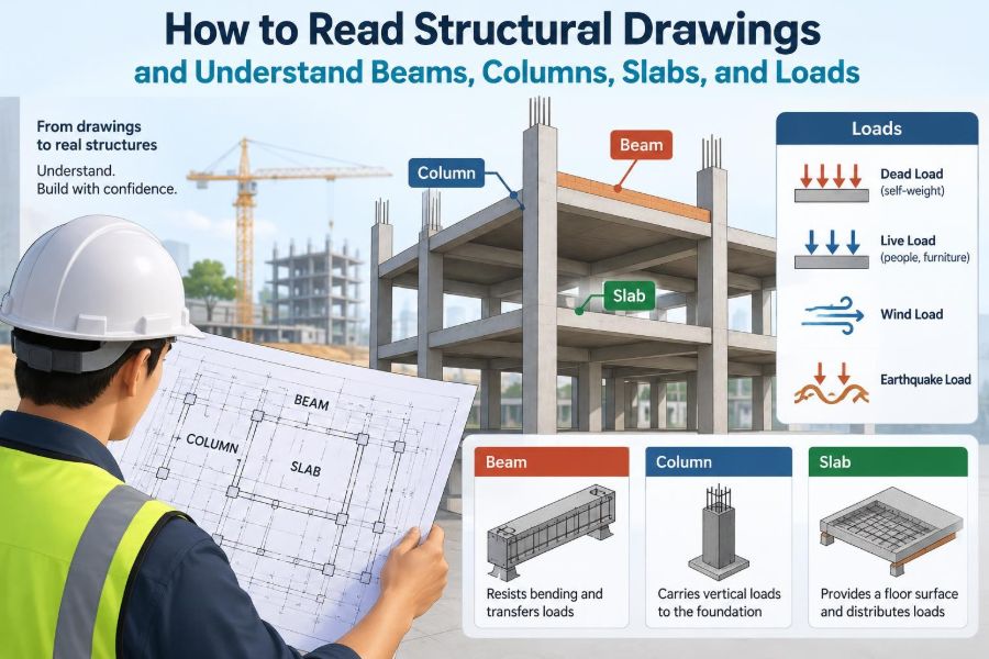

You are standing on a construction site with a set of drawings open in front of you. Lines, grids, symbols, notes, and abbreviated labels fill the page. A beam marked “B3” crosses a room, columns sit at grid intersections, and a slab note seems to refer to a detail somewhere else in the set.
For a student, this can feel like learning a second language. For a working professional outside structural design, it can be tempting to focus only on dimensions and assume the rest belongs to the engineer.
But structural drawings are not just graphic documents. They communicate the intended load path: the route by which the weight of people, furniture, walls, wind, and other actions travels safely down to the ground.
Learning to read them does not make someone qualified to redesign a building. It does, however, make coordination clearer, site conversations more useful, and potential misunderstandings easier to spot before concrete is poured or steel is installed.
🧭 Start with the purpose of a structural drawing
Structural drawings describe the parts of a building that resist loads and keep it stable: foundations, columns, beams, slabs, bracing, walls, connections, and reinforcement.
They work alongside architectural, mechanical, electrical, plumbing, and civil drawings. Architecture commonly explains the intended spaces and finishes; structural documents explain how the building is supported without interfering with that intent.
A drawing is therefore both a design record and a coordination tool. It must be read with its notes, schedules, details, and referenced sheets—not as an isolated floor plan.
📚 Know what belongs in a drawing set
Most structural packages contain several drawing types. The precise naming varies by office and project, so always use the sheet index rather than assuming a universal convention.
- General notes state materials, design assumptions, construction requirements, and abbreviations.
- Plans show the arrangement of framing at a particular level.
- Sections and elevations reveal vertical relationships that plans cannot show.
- Details enlarge critical junctions, such as a beam-to-column connection or slab edge.
- Schedules collect repeated information, including member sizes and reinforcement marks.
Before studying individual members, locate these sheets. They define the vocabulary used everywhere else.
🗂️ Read the title block and revision information
The title block identifies the project, drawing title, sheet number, scale, designer, and issue status. A sheet issued “for construction” has a different role from one issued for planning, coordination, or tender.
Revision clouds, triangles, or tables identify changes. On an active project, using an outdated structural drawing can create errors even when every measurement on that older sheet was once correct.
Check the issue date, revision identifier, and drawing status before extracting information. Digital document systems may also record superseded files, but the drawing itself should still be checked.
🔤 Learn the language of grids, levels, and references
Structural plans are organized around a grid: a network of numbered and lettered lines. A column described as being at “Grid B/4” is located where those two grid lines intersect.
Levels establish vertical position. They may be shown as elevations relative to a project datum, such as finished floor level, or with terms such as roof level and foundation level.
References connect drawings together. A callout might direct the reader to a section, detail, or another sheet. Following those links is essential because a plan often shows where something is, while a detail explains how it is built.
🧩 Understand line types and visual hierarchy
Line weight usually carries meaning. Heavy lines may indicate cut structural elements, while lighter lines can show items beyond the cut plane, grids, dimensions, or hidden work. The drafting convention differs between offices, so the legend has priority.
Dashed lines frequently indicate hidden elements, overhead framing, or alternate positions. A beam drawn with a dashed outline on one plan may be above the plan’s viewing level rather than absent.
Do not infer construction requirements from line weight alone. Pair every graphic clue with its label, note, and relevant section.
🧾 Decode common structural abbreviations
Abbreviations help drawings stay readable, but they can be confusing when copied between disciplines. Common examples include reinforced concrete, structural steel, finished floor level, top of slab, and bottom of beam.
Member marks are especially important. “C1,” “B2,” “W3,” or “F4” commonly refer to column, beam, wall, or footing types listed in a schedule. The mark is an identifier, not automatically a size.
A practical rule is simple: never guess an abbreviation when the drawing set provides a legend or schedule. One office’s shorthand may mean something different on another project.
🧱 Read plans as horizontal slices
A structural plan is a view looking down through a building at a chosen level. It may be a foundation plan, ground-floor framing plan, roof framing plan, or a plan specifically for slab reinforcement.
Elements that support that level may be shown prominently, while items below or above can appear differently. A roof beam, for example, is not necessarily visible on the floor framing plan beneath it.
First identify the plan level, then trace the grids and structural supports. This prevents a common error: treating all lines on a sheet as though they are physically in the same plane.
🏢 Recognize the main structural members
Most building structures can be understood as a hierarchy. Slabs and secondary members collect loads over broad areas; beams transfer them to columns or walls; vertical elements transfer them to foundations; foundations spread them into soil or rock.
Not every building follows this exact sequence. A flat slab may transfer loads directly to columns, a load-bearing wall may support floor joists, and a truss may span across several supports.
Still, identifying the hierarchy gives a reliable starting point: ask what each element supports and what supports it.
↔️ Understand what beams do
A beam is primarily a horizontal or sloping member that carries load across a span between supports. Under typical gravity loading, it bends: the upper and lower zones experience different internal stresses.
In reinforced concrete, steel reinforcement is placed where tensile forces are expected because concrete is comparatively weak in tension. In structural steel, the shape and connection design help the member resist bending, shear, and sometimes torsion.
A beam label may identify a standard type in a schedule, while a section or detail gives its depth, width, reinforcement, connection, or bearing requirement.
📏 Follow a beam from support to support
When reading a beam, find its start, end, and intermediate supports. Its apparent length on a plan is not enough; it may frame into a wall, stop at a column, continue over multiple supports, or change level at a step.
Then ask what loads frame into it. Smaller beams, joists, slab panels, masonry, façade supports, or concentrated equipment loads may all contribute.
A useful mental picture is a bookshelf. The shelf collects books along its length and delivers their weight to brackets or side supports. A real beam is more complex, but the transfer principle is similar.
🪜 Distinguish primary and secondary beams
Secondary beams often support slabs or decking and frame into larger primary beams. Primary beams then transfer accumulated load to columns, walls, or major supports.
This distinction affects coordination. A primary beam may be deeper because it carries load from several secondary members, making it more likely to affect ceiling space, duct routes, door heights, or façade openings.
Labels alone do not always announce the hierarchy. You can often infer it by tracing framing directions and observing which member receives other members.
🏛️ Understand columns as vertical load paths
Columns are vertical compression members that transfer load from beams, slabs, and upper floors to the foundations. They may be reinforced concrete, structural steel, timber, masonry, or composite construction.
On plans, columns are commonly placed at grid intersections because a regular grid simplifies framing. However, architectural requirements often create transfers, offsets, or irregular locations.
Column size can change from floor to floor. Lower columns frequently carry load from more storeys, though the final arrangement depends on the entire structural system and design criteria.
🧍 Watch for column continuity and offsets
A column that aligns vertically from roof to foundation gives a direct load path. If an upper column does not sit above a lower column or wall, its load must be redirected through a transfer element, often a deep beam, transfer slab, wall, or truss.
Transfers are not inherently wrong. They are common where open lobbies, parking layouts, or changing floor plans are required. They do, however, demand careful design and coordination because forces and deflections can be substantial.
When reviewing drawings, compare column locations between levels. An unexplained offset is a prompt to locate the relevant transfer detail, not a reason to assume an error.
🧱 Read slabs as area-supporting elements
A slab is a broad, plate-like structural element, usually horizontal, that carries floor loads over an area. It may be cast-in-place concrete, precast concrete, composite metal deck with concrete, timber panels, or another system.
Slabs transfer load in one main direction, two directions, or through a more complex pattern depending on their geometry, supports, stiffness, openings, and reinforcement.
Thickness notes are only part of the story. A slab drawing may also show drops, thickened strips, reinforcement zones, construction joints, openings, penetrations, and edge conditions.
🔀 One-way and two-way slab behavior
A one-way slab mainly spans between two opposite supports, much like a set of parallel planks resting on two beams. Its principal reinforcement generally follows the span direction.
A two-way slab distributes load toward supports in two directions. This behavior is common when a slab panel is supported on all four sides and its proportions allow meaningful action both ways.
Real slabs do not always behave as ideal textbook panels. Openings, unequal support stiffness, edge beams, and irregular shapes alter force flow. The engineer’s design drawings show the required reinforcement arrangement; they should not be recreated by visual intuition.
🕳️ Treat openings and penetrations seriously
Stairwells, lift shafts, service risers, ducts, pipes, and floor drains require openings in slabs and walls. Each opening interrupts the normal path of forces and may need trimming members, additional reinforcement, or a specially detailed edge.
A small site-requested core hole can be structurally significant if it cuts reinforcement, lies near a column, or occurs in a highly stressed zone. Its acceptability cannot be determined from a generic rule of thumb.
Do not move, enlarge, or create structural openings without the responsible designer’s review. The same caution applies to notches, chases, and unapproved attachments.
⬇️ Trace gravity loads to the ground
Gravity loads act downward. They include the permanent weight of the structure and finishes, plus variable loads from occupants, furniture, stored goods, movable partitions, and use-specific equipment.
Consider a simple office bay: floor loading acts on the slab; the slab transfers it to beams or directly to columns; columns transfer it to foundations; foundations distribute it into the supporting ground.
This route is the load path. If a member, support, connection, or foundation is missing from the chain, the drawing review should pause until the intended path is understood.
🎒 Separate dead, live, and imposed loads
Dead load is the relatively permanent weight of structural and fixed building components, such as slabs, beams, walls, finishes, and fixed services. Its value may change during design as material choices become final.
Live load, often called imposed load in many contexts, represents movable occupancy-related loading. Its magnitude depends on the intended use: a storage area, corridor, dwelling, roof, and plant room do not have the same expected loading conditions.
Drawings may state design loads, but the governing requirements depend on the applicable code, project location, and building use. Do not transfer values casually from one project or room type to another.
🌬️ Recognize lateral loads and stability systems
Buildings also resist sideways actions, including wind and, in some regions, earthquake effects. These loads can cause sway, overturning, and forces in connections and foundations.
The stability system may use reinforced concrete shear walls, steel braced frames, moment-resisting frames, cores, or a combination. A shear wall is not merely a partition; it may be a major structural element that resists in-plane lateral force.
Gravity framing and lateral framing sometimes overlap, but they should be understood separately. A beam that supports a floor is not automatically part of the system that stabilizes the building sideways.
⚖️ Understand reactions, not just applied loads
When a beam carries a load, its supports develop upward forces called reactions. In an idealized simple beam, the reactions balance the applied load and maintain equilibrium.
This idea helps when reading framing plans. A heavily loaded beam produces significant reactions at its columns or walls; those supports, in turn, affect the design of lower floors and foundations.
Structural engineering is therefore not only about adding member capacities. It is about maintaining a continuous, balanced force system from the point where load enters the building to the ground.
🔗 Read details before interpreting connections
A plan symbol can show that two members meet, but it rarely provides enough information to explain the connection. Details may specify bolts, welds, plates, reinforcement anchorage, stirrups, bearing lengths, dowels, grout, or concrete cover.
For reinforced concrete, bar placement and development length determine whether force can transfer as intended. For steel, connection geometry and fastener arrangement are part of the structural design, not workshop decoration.
Whenever a plan includes a detail callout, read it. The callout exists because that location has information too concentrated or too critical to fit on the plan.
🧷 Use schedules without losing the context
Schedules make repeated components efficient to document. A beam schedule may list each mark, section size, material grade, reinforcement, elevations, and remarks; a column schedule may show sizes that vary by storey.
Confirm the schedule’s scope. A beam mark can repeat only within one level, one block, or one drawing package. Check sheet notes and plan tags before applying it elsewhere.
| Document item | Best question to ask | Typical answer location |
|---|---|---|
| Beam mark | What are its size and reinforcement or steel section? | Beam schedule and section |
| Column mark | Does its size change with level? | Column schedule |
| Slab note | What thickness and reinforcement zone apply? | Slab plan and detail |
| Opening | What trimming or edge reinforcement is required? | Opening detail |
📐 Respect dimensions, scales, and written notes
Written dimensions take priority over scaling from a printed or on-screen drawing. Print settings, PDF viewers, and reproduction methods can alter apparent scale.
Dimensions may locate grids, faces of concrete, centre lines, finished surfaces, or bolt centres. Read the extension lines and notes carefully to identify what is actually being measured.
If dimensions conflict with a graphic appearance, do not choose whichever seems more convenient. Follow the project’s document-control process and seek clarification from the responsible design team.
🔍 Compare structural and architectural drawings
Coordination begins by overlaying the structural logic with the architectural intent. Check that columns do not obstruct critical circulation, beams do not clash with ceiling heights, and walls shown as structural align with their architectural counterparts.
Differences are not always mistakes. An architectural plan may simplify hidden structure, while a structural plan may omit nonstructural partitions. The goal is to understand each drawing’s purpose before flagging a discrepancy.
Particular attention is needed around stairs, lifts, large openings, cantilevers, façade supports, rooftop plant, and transfer levels because these areas often involve several disciplines.
🛠️ Coordinate services before construction locks in
Mechanical and electrical services compete for the same ceiling and floor zones as beams, braces, and reinforcement. A duct routed through a shallow ceiling may clash with a deep beam; a pipe sleeve may interfere with a slab band or beam reinforcement.
Early coordination can accommodate services through planned openings, adjusted routes, or changed member geometry. Late cutting is much riskier and may invalidate the intended load path.
On site, “it is only a small hole” is not a structural assessment. Use approved coordination drawings and raise clashes before work proceeds.
🚧 Recognize the limits of a drawing review
Reading drawings well is not the same as designing, inspecting, or approving structural work. Material properties, construction sequence, temporary works, soil conditions, and connection behavior can affect safety in ways a quick plan review cannot resolve.
Temporary conditions deserve special care. Formwork, propping, lifting, excavation support, and partially completed frames may carry loads differently from the finished building.
If a drawing is unclear, a member is damaged, site conditions differ from assumptions, or a change is proposed, the appropriate response is to refer the matter to the responsible structural professional—not to improvise.
⚠️ Avoid the most common reading mistakes
Many drawing errors arise from rushing rather than from difficult mathematics. The following habits reduce avoidable misunderstandings:
- Reading a beam size without checking its level, section, and support condition.
- Assuming a dashed element is unimportant or nonstructural.
- Using a schedule from the wrong floor or revision.
- Ignoring a detail reference because the plan “looks clear.”
- Confusing architectural walls with load-bearing or lateral-resisting walls.
- Scaling a drawing instead of using stated dimensions.
- Changing openings, reinforcement, or connections without documented approval.
Each mistake can interrupt coordination or compromise the intended construction. Careful cross-referencing is faster than correcting built work.
📝 Build a repeatable drawing-review routine
A consistent sequence prevents readers from getting lost in the page. Begin broadly, then move toward individual members and details.
- Check the sheet title, issue status, revision, scale, and general notes.
- Identify grids, levels, and the structural system for the area.
- Locate columns, walls, beams, slabs, openings, and foundations.
- Trace gravity and lateral load paths where relevant.
- Read schedules, sections, and details for every marked element.
- Compare adjoining levels and other disciplines for coordination conflicts.
- Record questions clearly, with sheet numbers, grid locations, and mark references.
This process works for students learning fundamentals and for project teams reviewing complex packages. The depth changes, but the logic remains sound.
🧠 Practice with a simple framing example
Imagine a rectangular room with a concrete slab supported by two parallel secondary beams. Those beams frame into deeper primary beams at each end, and the primary beams sit on four columns.
To read the layout, start at the slab. Determine its thickness and spanning direction, then identify the secondary beams collecting its load. Next, see where those beams frame into the primaries, and finally follow the primary-beam reactions into the columns and foundations.
Now add a stair opening near one corner. The normal slab path is interrupted, so the drawings may show trimming beams or extra reinforcement around the opening. This small example demonstrates why plans, sections, and details must be read together.
🎓 Know what confident reading really means
Confidence does not mean instantly knowing every symbol. It means knowing how to find the answer: locate the note, follow the reference, verify the revision, compare levels, and ask a precise question when information is missing.
A useful question is more than “What does this mean?” Try: “On structural sheet S-___, at Grid ___, does beam mark ___ bear on the wall or frame into the column shown on the adjacent section?” Specific questions lead to faster, safer clarification.
Over time, patterns become familiar. Yet every project still deserves fresh attention because systems, materials, terminology, and detailing conventions vary.
🏁 The core principle: follow the load path
The most reliable way to understand structural drawings is to see them as a connected story of forces. A slab gathers area load, beams or walls collect it, columns and walls carry it downward, and foundations transfer it to the ground. Lateral systems provide a separate but equally essential route for sideways actions.
Plans show arrangement, schedules identify repeated members, sections reveal vertical geometry, and details explain critical construction. None replaces the others.
When a line, symbol, or member seems confusing, return to the central question: what load does this element carry, and where does that load go next? That question turns a crowded sheet into an understandable structural system.
Reading structural drawings well means connecting every member, note, and detail to a safe and continuous path for forces. With patient cross-referencing and respect for design responsibility, the drawings become a practical map of how a building stands. 🏗️📐🔎