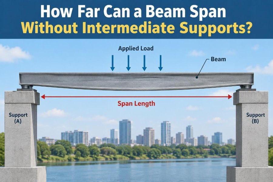

A homeowner wants an open-plan kitchen with no post between the island and living room. A warehouse designer wants a clear floor for forklifts. A deck builder wants the view beneath a balcony unobstructed. In each case, the question sounds simple: how far can the beam go without a support in the middle?
The tempting answer is a single number. People often ask for a “maximum span” as though every beam of a given material performs the same way. But a beam is not judged by distance alone. Its span depends on what it carries, how it is supported, its shape, material, connections, and the amount of movement the structure can tolerate.
A beam can be strong enough not to break and still be unsuitable because it sags noticeably, cracks finishes, vibrates under foot traffic, or overloads its supporting columns. Conversely, a deep engineered beam may cross a surprisingly long distance safely when its loads and details are properly designed.
Understanding the variables behind beam span helps students interpret structural behavior and helps practitioners communicate clearly with clients, architects, and contractors. It also makes one principle hard to forget: removing a support does not remove the load—it changes where that load must go.
📏 Span Is More Than the Empty Distance
A beam’s span is the distance between points that provide support. Depending on the calculation and drawing convention, engineers may use the center-to-center distance between supports, the clear distance between their faces, or an effective span defined by a design standard.
That distinction matters because the bending demand increases rapidly as the unsupported distance grows. A beam over a 6 m opening does not behave exactly like one over 5 m simply because the difference is 1 m; the added length can create a disproportionately larger bending moment and deflection.
“Without intermediate supports” means the beam transfers its load directly to supports at its ends, such as walls, columns, girders, or frames. Those end supports must themselves have a continuous load path down to adequate foundations.
🧱 A Beam Is Part of a Load Path
No beam works in isolation. Gravity loads move from roof or floor surfaces into joists, then into beams, then into columns or bearing walls, then into foundations, and finally into the ground.
When a middle column is removed, its share of load is not eliminated. The replacement beam takes on load over a larger tributary area—the area of floor or roof whose weight is delivered to that beam. The end supports may also receive much larger reactions.
This is why a renovation cannot safely stop at choosing a larger beam. The posts, wall framing, footings, soil bearing capacity, and connections may all require assessment. A strong beam above a weak support is not a complete structural solution.
⚖️ The Loads a Beam Must Carry
Beam design begins by identifying loads. Dead load is the relatively permanent weight of structural members, finishes, ceilings, roofing, services, and fixed equipment. Live load comes from people, furniture, movable storage, or use of the space.
Roofs may also need to resist snow, rain ponding, maintenance activity, and wind effects. In some structures, equipment loads, vehicle loads, partitions, suspended mechanical systems, or seismic actions govern the design.
Loads are converted into a line load on the beam, often expressed as force per unit length. A beam supporting floor joists from both sides generally carries more than a beam supporting joists from one side only. The building’s intended use therefore changes the answer to the span question.
📐 Tributary Width Sets the Beam Demand
Imagine a floor beam with joists framing into it from each side. If the joists extend 3 m to the left and 3 m to the right, the beam’s tributary width is commonly based on half of each adjacent joist span: 1.5 m plus 1.5 m, or 3 m total.
If the floor load is uniformly distributed, multiplying that area load by tributary width gives an approximate line load on the beam. A wider tributary width means a heavier beam load even when the beam span stays unchanged.
This explains why copying a beam size from another project is risky. Two openings that look identical can demand very different beams because one supports a narrow roof strip and the other supports two storeys of floor framing.
📈 Why Longer Spans Become Hard Quickly
For a simply supported beam carrying a uniform load, the maximum bending moment is commonly represented by the relationship M = wL²/8, where w is line load and L is span. The key insight is the squared span term.
Double the span while holding the load per metre constant, and bending moment becomes roughly four times larger. In a real building, the longer beam may also collect load from a larger area, making the increase even more demanding.
Deflection rises faster still. For a simple, uniformly loaded beam, elastic deflection varies with approximately the fourth power of span when section stiffness is unchanged. That is why modest-looking increases in opening width can require much deeper or stiffer members.
🏹 Bending Creates Compression and Tension
When a typical simply supported beam sags under downward gravity load, its top fibers shorten in compression while its bottom fibers stretch in tension. Between them lies the neutral axis, where longitudinal bending stress changes sign.
Different materials respond differently to these stresses. Steel has similar strength in tension and compression, while reinforced concrete uses steel reinforcement because plain concrete is weak in tension. Timber behavior depends strongly on grain direction, defects, moisture, and grade.
A deeper beam generally resists bending more efficiently because more material is placed farther from the neutral axis. This is the practical reason a deep section can outperform a much wider but shallow one.
✂️ Shear Matters Near the Supports
Bending moment is often largest around midspan, but shear force is typically greatest near supports. Shear can cause different failure mechanisms, including web yielding in steel members, splitting or rolling shear in timber, and diagonal cracking in concrete.
A beam selected only for midspan bending can be inadequate at its ends. Engineers check both actions, along with localized effects where concentrated loads or reactions enter the member.
Notches, holes, and poorly located penetrations are especially dangerous near high-shear zones. A service opening that looks small to a plumber may remove a critical portion of a beam’s web or timber depth.
📉 Strength Is Not the Same as Serviceability
Strength limit states address collapse or instability under factored design loads. Serviceability addresses performance under normal use: deflection, vibration, cracking, settlement-related movement, and damage to finishes.
A floor beam may have adequate calculated strength yet feel springy when people walk across it. A roof beam may remain safe but sag enough to cause drainage problems. A beam beneath brittle finishes may produce cracks at much smaller deflections than the beam’s ultimate capacity would suggest.
For many residential floors and long roof members, deflection or vibration—not material strength—can govern the final size. The acceptable limit depends on occupancy, finishes, partition layout, and applicable design requirements.
📊 A Quick Guide to the Main Span Variables
| Variable | What it changes | Typical design consequence |
|---|---|---|
| Beam span | Bending and deflection demand | Longer spans usually need deeper or stiffer members |
| Tributary width | Load delivered to the beam | Wider supported area increases line load |
| Material and grade | Strength, stiffness, durability | Identical dimensions can have different capacities |
| Section depth | Bending resistance and stiffness | Depth is often more effective than added width |
| Support condition | Moments, reactions, and rotation | Simple, continuous, and fixed beams behave differently |
| Occupancy and finishes | Serviceability requirements | Vibration and deflection limits may become decisive |
This table is a screening tool, not a sizing method. Beam design requires the variables to be considered together rather than one at a time.
🌲 Solid-Sawn Timber Has Practical Limits
Solid timber is widely used because it is accessible, workable, and attractive when exposed. Its capacity, however, varies with species, grade, dimensions, duration of loading, moisture condition, and the presence of knots, checks, slope of grain, or damage.
For a given width, increasing depth is usually the most effective way to improve timber beam performance. Yet available lumber sizes, transport, fire requirements, shrinkage, and connection detailing can constrain the solution.
Long, heavily loaded clear spans can become impractical with conventional sawn lumber because a member deep enough to control deflection may be difficult to source or integrate architecturally. That is often where engineered wood becomes useful.
🪵 Engineered Wood Extends Clear Spans
Laminated veneer lumber (LVL), glued laminated timber (glulam), parallel strand lumber, and wood I-joists are manufactured to provide more consistent properties than ordinary solid-sawn members. They can be produced in larger depths and lengths, enabling efficient long-span framing.
A glulam may be chosen where the beam will remain visible, while LVL is common in concealed residential framing. Each product has manufacturer-specific capacities, bearing requirements, connection details, and exposure limitations.
Engineered wood is not automatically interchangeable. A deeper LVL, a wide glulam, and a built-up timber beam can have very different stiffness, fire behavior, camber availability, and installation requirements even if they occupy a similar space.
🔩 Steel Delivers High Strength in Compact Sections
Steel beams can carry substantial loads over long distances with sections that are often shallower than comparable timber alternatives. Wide-flange beams are common because their flanges efficiently resist bending while the web carries much of the shear.
But steel’s apparent slimness should not be mistaken for simplicity. The beam may need protection against fire and corrosion, lateral bracing to prevent instability, carefully designed connections, and bearing plates where reactions are concentrated.
Steel also deflects. A beam that is adequate in strength may still require a larger section to limit movement. For exposed architectural steel, fabrication tolerances, camber, erection sequence, and visual alignment deserve early attention.
🧱 Reinforced and Prestressed Concrete Behave Differently
Reinforced concrete beams combine concrete’s compressive capacity with reinforcing steel placed where tension is expected. They can form monolithic systems with slabs and columns, which is advantageous in many buildings.
Concrete beams are relatively heavy, so their self-weight becomes a significant load as spans increase. Cracking, long-term creep, shrinkage, reinforcement detailing, and construction-stage support all influence deflection and performance.
Prestressed concrete introduces pre-compression to counter tensile stresses under service loads. It can achieve longer spans efficiently, but it requires specialized design, fabrication, stressing operations, and quality control. It is not a simple field substitution for ordinary reinforced concrete.
🔄 Support Conditions Change the Answer
A beam resting freely on two supports is usually modeled as simply supported. It develops positive bending moment and downward deflection near the middle. This is a useful starting model, but many real systems are more complex.
Continuous beams pass over multiple supports, reducing positive midspan moment while introducing negative moment over interior supports. Fixed-end connections can reduce midspan deflection, but only if the supports and connections truly provide rotational restraint.
Assuming continuity that construction cannot deliver is unsafe. Conversely, ignoring genuine continuity can lead to unnecessarily conservative results. The model must match the actual framing, connection stiffness, and construction sequence.
🧭 Cantilevers Are Not Ordinary Spans
A cantilever projects beyond a support with no support at its free end. Balconies, canopies, and roof overhangs use this arrangement, but their critical bending moment occurs at the fixed support rather than at midspan.
Deflection and rotation can be pronounced because the support must resist both vertical force and moment. The backspan, anchorage, reinforcement, connection, and supporting structure are all part of the system.
Calling a cantilevered member “a beam with one support” misses the essential issue: it needs a reliable moment-resisting connection. A simple bearing seat cannot create a cantilever.
🪢 Lateral Stability Can Govern Steel and Timber Beams
A beam compressed along its top edge may twist sideways before its material reaches its nominal bending strength. This instability is known as lateral-torsional buckling, and it is particularly relevant for unbraced steel beams and slender timber members.
Floor decking, roof sheathing, joist blocking, purlins, or dedicated bracing can restrain the compression edge. The exact benefit depends on how effectively these elements are connected and whether they remain in place during construction.
A beam can therefore have a different safe capacity before and after a floor diaphragm is installed. Temporary bracing and erection-stage checks are not optional details; they can control construction safety.
🧩 Connections Must Transfer the Forces
Bolts, welds, hangers, bearing seats, plates, screws, and anchors transfer forces from one element to another. If the connection cannot develop the beam’s reaction, shear, or moment demand, increasing the beam size alone accomplishes little.
Timber beams need adequate bearing length and protection against crushing perpendicular to grain. Steel connections need checks for bolt shear, bearing, block shear, weld capacity, and supporting-member strength. Concrete connections require appropriate reinforcement development and anchorage.
Connection geometry also affects constructability. A beam that technically works but cannot be lifted into place, bolted, inspected, or protected from moisture is a poor project solution.
🏛️ End Reactions Can Overload Columns and Footings
For a uniformly loaded simple beam, each end support takes approximately half the total vertical load. As the beam gets longer or carries a wider tributary area, those reactions rise.
In an open-plan renovation, a new beam may concentrate load onto two posts that did not previously exist. Those posts may need larger headers, reinforced stud packs, steel columns, or new foundations below them.
Checking only the visible opening is a common error. The design question is not merely “Can this beam span?” but “Can the whole support chain safely receive the resulting forces?”
🏠 Residential Openings Need Careful Framing Review
Removing a wall in a house is a familiar example. Some walls are non-load-bearing, but others support floor joists, roof trusses, another wall above, or a combination of these. The direction of joists often provides clues, but it is not conclusive by itself.
Loads may be discontinuous or concentrated, such as a point load from a beam above landing on the wall being removed. A standard header table may not apply when the building has unusual geometry, multiple levels, heavy roof coverings, or altered framing.
For existing houses, hidden conditions matter: previous modifications, notched framing, undersized footings, decay, termite damage, and settlement can change the appropriate intervention.
🏭 Commercial Floors and Roofs Bring Different Demands
Clear spans in offices, retail spaces, workshops, and warehouses are often driven by flexibility: fewer columns make layouts, equipment movement, and future alterations easier. The structural trade-off is that beams, trusses, or girders usually become deeper, heavier, or more expensive.
A storage area may impose substantially different loads from a meeting room. Rooftop plant, suspended services, façade loads, and openings for ducts can also create concentrated demands that a simple span estimate overlooks.
Long-span systems are often coordinated early with architecture and building services. A beam that occupies the ceiling zone may conflict with ducts, sprinklers, lighting, and required headroom, influencing the structural system choice.
🌉 Trusses Can Beat Solid Beams for Long Spans
A truss uses a triangulated arrangement of members, placing many elements primarily in tension or compression rather than relying on one solid member to resist bending. This can provide an efficient solution for long roof spans and selected floor applications.
Its depth is part of its strength. A truss may be deeper than a rolled steel beam, but it can use material efficiently and create openings for some services. It also introduces many connections that must be designed and fabricated accurately.
Trusses are not always best. Their diagonal members can obstruct large ducts, their depth can challenge architectural spaces, and field modifications are particularly hazardous. Cutting or removing a truss web member without engineering review can fundamentally change its force path.
📐 Deeper Usually Beats Wider
For bending, moving material away from the neutral axis is highly effective. That is why I-shapes, box sections, deep glulams, and trusses exist: they place material where it contributes most to resistance and stiffness.
Adding width can help with bearing, shear, local stability, and connections, but it usually does not improve bending stiffness as efficiently as adding depth. This is a useful conceptual rule, not a substitute for calculation.
The architectural cost of depth is real. A deeper beam can reduce headroom, complicate services, and affect façade levels. Engineers balance structural efficiency against these spatial constraints rather than maximizing any one property in isolation.
📏 Camber Can Offset Expected Deflection
Camber is a deliberate upward curvature introduced into a beam before loading. Under dead load, the beam settles toward level rather than appearing permanently sagged.
Camber is often used for long steel beams, trusses, and some engineered timber members. It must be specified carefully because excessive camber can create floor-level problems, ceiling conflicts, or unexpected drainage slopes.
Camber does not add strength. It is a geometry-control measure, and the designer still checks deflection under service loads. It also cannot reliably eliminate all long-term movement from creep, shrinkage, or changing occupancy.
🌡️ Time, Moisture, and Temperature Affect Performance
Materials do not remain unchanged after installation. Timber can shrink or swell with moisture changes, concrete experiences creep and shrinkage, and steel expands or contracts with temperature. Long members can make these movements more noticeable.
Sustained loads can increase long-term deflection, especially in timber and concrete systems. Connections and finishes must accommodate expected movement where appropriate rather than assuming a beam stays perfectly fixed forever.
Exposure conditions matter too. Exterior timber needs durable detailing, steel may need corrosion protection, and concrete needs suitable cover and durability provisions. A theoretically adequate span is not durable if the material deteriorates in its environment.
🛠️ Construction Sequence Can Change Beam Forces
During construction, a beam may temporarily support loads in a configuration different from its final design. Removing a wall before shoring is installed can cause immediate distress. Placing wet concrete on formwork can impose major temporary loads before the system gains its intended capacity.
Temporary supports, lifting points, lateral restraints, and staged loading should be planned, particularly for long or heavy members. Contractors need enough information to understand what can be removed, when it can be removed, and what must remain braced.
Existing structures deserve special care because load paths can be difficult to verify. Field conditions should be checked against assumptions before irreversible work begins.
🚫 Common Shortcuts That Produce Bad Answers
- Using a span table outside its stated conditions: tables may assume a particular species, grade, spacing, load, support condition, and deflection criterion.
- Sizing from depth alone: a “deep-looking” beam may still be inadequate for its load, bracing, or connection requirements.
- Ignoring point loads: a post, trimmer, or equipment support can govern a beam designed for uniform loading.
- Assuming a wall is nonstructural: hidden framing or loads from above may make it critical.
- Cutting holes after installation: service penetrations can reduce shear or bending capacity substantially.
These mistakes are attractive because they simplify a complicated question. Good engineering does not reject simple tools; it uses them only within the limits for which they were intended.
🧮 A Sensible Preliminary Design Workflow
- Define the opening, support locations, and whether the member is simple, continuous, or cantilevered.
- Trace all loads that reach the beam, including self-weight, floor or roof area, walls above, and concentrated loads.
- Establish tributary widths and applicable load combinations under the governing design framework.
- Select realistic material options and preliminary depths that fit the building geometry.
- Check bending, shear, bearing, deflection, vibration, stability, connections, and supports.
- Coordinate fire protection, durability, services, erection, and the foundation load path.
For students, this workflow prevents tunnel vision on a single bending formula. For professionals, it provides a useful sequence for early feasibility discussions before detailed analysis.
📚 Span Tables Are Screening Tools, Not Universal Rules
Prescriptive span tables can be valuable for conventional construction. They offer quick, code-based solutions for narrowly defined conditions and help avoid unnecessary calculation in routine work.
They become unreliable when geometry, loads, material grade, support conditions, or exposure fall outside their assumptions. A table entry may not account for a roof point load, a large opening in a bearing wall, a concentrated reaction, or a serviceability requirement driven by sensitive finishes.
Read the notes as carefully as the numbers. The table’s limitations are often where the real engineering question begins.
👷 When a Structural Engineer Should Be Involved
Professional input is appropriate when a project removes bearing walls, creates large openings, adds levels, supports heavy equipment, alters foundations, uses unusual materials, or shows signs of distress. Local permit requirements may also require engineered drawings for structural alterations.
Warning signs include sagging, cracking that is widening or patterned around openings, bowed walls, corroded steel, decayed timber, or temporary supports carrying unknown loads. These signs do not identify a cause by themselves, but they justify investigation.
A site-specific engineer can inspect the actual conditions, establish design assumptions, and provide details for the beam, supports, connections, and foundation path. That is more useful—and safer—than relying on a generic online beam size.
🧠 The Core Principle: Span Is a System Question
There is no universal distance that a beam can span without intermediate support. The answer emerges from the relationship between span, loads, section properties, material behavior, support conditions, serviceability limits, stability, connections, and foundations.
Longer clear spans are absolutely achievable. They may call for deeper sections, engineered wood, steel, concrete, trusses, stronger end supports, or a different structural arrangement. The best choice depends on the building’s use, geometry, construction method, budget, and architectural priorities.
When evaluating any proposed opening, start by tracing the load path and defining the actual loads. Only then does selecting a beam become a meaningful engineering decision rather than a guess based on distance alone.
A beam can span only as far as the complete structural system can safely carry, restrain, and support it. That is the principle behind every reliable clear-span design. 🏗️📐🔩