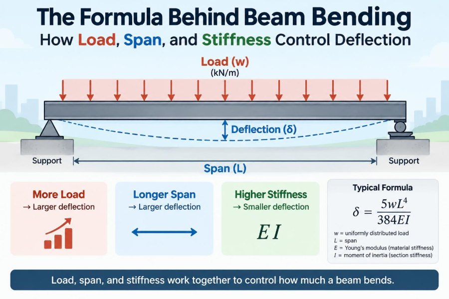

A floor that feels slightly springy underfoot, a shelf that visibly sags beneath books, and a bridge deck that moves as traffic passes all reveal the same structural behavior: beam bending.
That movement is not automatically a sign of failure. Every real beam deforms under load. The engineering question is whether the amount of deformation—called deflection—is small enough for safety, serviceability, durability, and the people using the structure.
For students, beam-deflection formulas can seem like a collection of cases to memorize. For practicing engineers, the same formulas become rapid judgment tools: a way to spot when a long member, heavy load, flexible material, or weak connection deserves closer attention.
The central relationship is remarkably consistent. Load makes a beam bend more; span amplifies that bending dramatically; and stiffness resists it. Understanding how those three ingredients interact turns equations into structural intuition.
🧭 What Deflection Actually Means
Deflection is the displacement of a point on a structural member from its original, unloaded position. For a horizontal beam carrying gravity load, it is usually measured as a downward vertical movement, often greatest near midspan.
Deflection is different from stress. Stress describes internal force intensity within the material; deflection describes the resulting change in shape. A beam can satisfy a strength check and still deflect enough to crack finishes, pond water, disturb machinery, or feel uncomfortable.
🏗️ Why Beams Bend Under Vertical Load
When a load acts on a beam, its supports develop reactions that oppose that load. Between the loads and supports, the beam develops internal shear force and bending moment. The bending moment is what curves the member.
Imagine gently bending a ruler. The upper fibers shorten in compression while the lower fibers lengthen in tension, with a surface between them undergoing little or no longitudinal strain. This is the neutral axis. The larger the bending moment, the greater the curvature the beam must develop.
📐 The Core Beam-Deflection Relationship
For a slender, linearly elastic beam under small deflections, the governing relationship is commonly written as EI d²v/dx² = M(x), with sign conventions varying by textbook. Here, v is deflection, M(x) is bending moment, E is elastic modulus, and I is second moment of area.
The key quantity is flexural rigidity, EI. A high flexural rigidity means a given bending moment creates relatively little curvature. Deflection formulas are the result of integrating curvature along the beam while applying the actual support conditions.
⬇️ Load Magnitude Sets the Starting Demand
Within ordinary elastic analysis, deflection is proportional to load. Double a point load on the same beam, and its elastic deflection doubles. Double a uniformly distributed load, and the corresponding deflection also doubles.
This linearity is useful, but conditional. It assumes the beam remains in the elastic range, support conditions do not change, and geometry changes are modest. Cracking in reinforced concrete, yielding in steel, slip in a connection, or very large movement can make the real response depart from a simple proportional rule.
📏 Span Has an Outsized Influence
Span is often the quickest clue to a deflection problem. For many common beam cases, maximum deflection varies with the third or fourth power of span. That exponent means lengthening a member is far more consequential than intuition initially suggests.
For example, a simply supported beam with a uniform load has a maximum deflection proportional to L⁴. If its span doubles while its load per unit length and stiffness remain unchanged, the calculated deflection becomes sixteen times larger. This is why architectural demands for open, column-free rooms require early structural coordination.
🧱 Stiffness Is the Beam’s Resistance to Curvature
Stiffness is not a single material property. In bending, it comes from the combination EI. The modulus E describes how strongly a material resists strain; the geometric term I describes how effectively the cross-section places material away from the neutral axis.
A steel beam and a timber beam of similar outside dimensions can behave very differently because their moduli differ. Two steel beams of equal area can also deflect very differently because their shapes produce different values of I. Material and geometry must be considered together.
🧪 Elastic Modulus: The Material Contribution
Elastic modulus, usually called Young’s modulus, relates stress to strain in a material’s linear elastic range. A higher modulus means the material develops less strain under the same stress, contributing to lower curvature and deflection.
Steel has a relatively high and predictable modulus. Timber varies with species, grade, moisture, grain direction, and duration of loading. Concrete introduces another layer of complexity because cracking and time-dependent behavior can substantially reduce effective bending stiffness under service conditions.
📦 Second Moment of Area: Why Shape Matters
The second moment of area, I, is sometimes called the area moment of inertia. It is a geometric property of a cross-section, measured about the axis of bending. It is not the same as mass moment of inertia used in dynamics.
Material near the neutral axis contributes relatively little to I; material farther away contributes much more. This explains the efficiency of I-shapes, box sections, and deep joists. Their flanges or walls place a substantial portion of material where it can resist bending effectively.
📚 A Simple Shape Comparison
Consider a rectangular beam with width b and depth h, bending about its strong horizontal centroidal axis. Its second moment of area is I = bh³/12. Depth is cubed, while width is only linear.
If the depth is doubled while width is unchanged, I becomes eight times larger. If the width is doubled instead, I only doubles. Increasing depth can therefore be a highly efficient way to limit deflection, though it may affect headroom, fire protection, buckling restraint, architecture, and cost.
🔩 Support Conditions Change the Whole Problem
A beam’s supports do more than hold it up. They determine which translations and rotations are restrained, and those restraints control the bending-moment diagram and deflected shape. The same beam under the same load can deflect very differently when its end conditions change.
A simple support allows end rotation; a fixed support restrains rotation and develops end moments; a cantilever has one fixed end and one free end. Real connections may fall somewhere between ideal pinned and fully fixed behavior, so assuming a degree of fixity without detailing evidence can be misleading.
🪜 Simply Supported Beams: The Familiar Case
For a simply supported beam of span L carrying a central point load P, the maximum deflection occurs at midspan:
δmax = PL³ / (48EI)For the same beam carrying a uniform load w over its full span:
δmax = 5wL⁴ / (384EI)These equations are powerful because they expose the governing trends directly: deflection rises with load and span, and falls as E or I increases. They apply only to the stated load arrangement and ideal support model.
🚩 Cantilevers Need Special Attention
A cantilever is fixed at one end and free at the other. Balconies, canopy arms, sign supports, diving boards, and many projecting structural elements behave this way. The maximum deflection occurs at the free tip, where movement is easiest to see.
For a cantilever with a tip load P, δmax = PL³/(3EI). With a full-length uniform load w, δmax = wL⁴/(8EI). The large coefficients and absence of a second support make cantilever serviceability especially sensitive to span, connection stiffness, and construction tolerances.
🧷 Continuous Beams Can Be Stiffer—With Conditions
A beam spanning over multiple supports develops negative bending moments over interior supports and smaller positive moments in the spans. Compared with separate simple spans of equal length, continuity often reduces midspan deflection and can use material more efficiently.
That benefit depends on genuine continuity. Connection flexibility, support settlement, phased construction, cracking, or an expansion joint can alter the intended behavior. Continuity also shifts demand toward support regions, so a lower midspan deflection does not eliminate the need for strength and detailing checks there.
🌧️ Point Loads and Distributed Loads Bend Differently
A point load concentrates its effect at one location: a person standing on a plank, a wheel load, or a piece of equipment on a platform. A distributed load spreads over length: self-weight, a roof finish, storage over an area, or floor occupancy converted into line load on a joist.
Two load cases with the same total load need not produce the same maximum moment or deflection. Location matters. A point load near the middle of a simple span generally produces more deflection than the same load placed close to a support, because the beam’s bending demand is highest around midspan.
🧮 Superposition Makes Complex Loading Manageable
In linear elastic analysis, superposition allows the response from several loads to be added. An engineer can calculate deflection from self-weight, finishes, a partition load, and an equipment load separately, then combine the compatible responses.
This is not permission to add formulas carelessly. The method requires linear behavior and consistent boundary conditions. It becomes less reliable when cracking, contact changes, yielding, large displacements, or nonlinear connections materially affect the member.
⚖️ Strength and Serviceability Are Different Checks
Strength design asks whether the member, connections, and supports can resist the required actions without unacceptable failure. Serviceability asks whether the structure remains functional and acceptable in normal use. Deflection is primarily a serviceability concern, although excessive movement can contribute to secondary damage or instability-related issues.
A floor beam may have ample bending strength but still create complaints because ceilings crack, brittle partitions are distressed, doors bind, or occupants sense vibration. Conversely, a stiff beam may meet deflection expectations while still requiring careful checks for bending, shear, lateral stability, and bearing.
📋 Deflection Limits Are Context-Specific
Design guidance often expresses acceptable movement as a fraction of span, such as a limit written in the form L/number. The appropriate criterion depends on the applicable code, member type, load combination, finishes, partitions, roofing system, drainage requirements, and use of the building.
There is no single universal ratio that can be applied to every beam. A roof with brittle finishes or drainage-sensitive geometry may demand different control from an industrial platform. Project requirements and governing standards must be checked rather than relying on a remembered rule of thumb.
🏠 The Often-Missed Role of Self-Weight
Every beam carries its own weight. That load may be small for a short light member, but it becomes significant as spans and section sizes increase. A deeper beam may reduce deflection through a higher I, while also adding dead load that increases bending demand.
For a uniform prismatic beam, self-weight can be represented as a uniform line load based on material unit weight and cross-sectional area. This creates a useful design reminder: stiffness improvements should be evaluated with their added weight, not treated as free improvements.
🪵 Time-Dependent Deflection in Timber
Timber can experience additional movement under sustained loading, commonly described as creep. Moisture changes, grain orientation, member grade, and service environment also influence behavior. A floor that looks acceptable immediately after construction may show more long-term deflection under permanent load.
Design methods for timber therefore commonly distinguish short-term and long-term effects through code-based adjustment approaches. Field conditions matter: a well-protected interior member and an exposed, moisture-variable member should not automatically be expected to perform alike.
🧱 Cracking and Creep in Reinforced Concrete
Concrete is strong in compression but weak in tension. When tensile zones crack under service loading, the effective flexural stiffness of a reinforced concrete member can be lower than that implied by its gross, uncracked section. Reinforcement continues to carry tension and provides post-cracking stiffness, but the behavior changes.
Concrete also creeps and shrinks with time. Sustained loads can produce increasing deflection, while shrinkage can influence curvature and restraint effects. Reliable concrete deflection assessment uses the method required by the applicable design standard and should account for construction sequence where it matters.
🔧 Steel Beams: Stiff Yet Not Automatically Problem-Free
Steel’s high elastic modulus often makes it attractive for long spans, but stiffness is still governed by EI, not E alone. A shallow steel section can be strong enough yet too flexible for a demanding serviceability condition.
Composite action with a properly connected concrete slab can increase stiffness in some floor systems, but it must be designed as composite construction rather than assumed. Camber, erection sequence, slab cracking, diaphragm behavior, vibration, and connection details can all affect the final in-service response.
📉 Shear Deformation Is Usually Small—but Not Always
The familiar beam formulas emphasize bending deformation. For long, slender beams, that is often appropriate. For deep beams, short spans, sandwich panels, low-shear-stiffness materials, or members with flexible web behavior, shear deformation can make a noticeable contribution to total deflection.
This is one reason formulas should be matched to the member and theory being used. A model based only on bending may underpredict movement when the member is not slender enough for that assumption to hold.
🧍 Vibration Is Related to Deflection, Not the Same Thing
A flexible floor may be acceptable under a static deflection criterion yet still feel lively when people walk across it. Static deflection measures displacement under a sustained or slowly applied load; vibration concerns dynamic response, including frequency, damping, mass, and the pattern of excitation.
Stiffening a beam often helps both concerns, but it does not guarantee a satisfactory vibration response. Long-span floors, pedestrian structures, and areas supporting sensitive equipment may require a separate dynamic evaluation.
🧩 Connections, Bearings, and Foundations Also Move
Hand calculations often treat supports as immovable points. In an actual structure, bolts can slip, plates can flex, connections can rotate, bearing pads can compress, columns can shorten, and foundations can settle. The measured deflection of a floor system may include all of these movements.
Where serviceability is sensitive, model the complete load path rather than only the beam. A very stiff member attached to a flexible supporting system will not behave like a perfectly supported textbook beam.
🧠 A Worked Hypothetical Comparison
Suppose two simply supported rectangular joists have the same width, material, span, and uniform line load. Joist B is twice as deep as Joist A. Because I = bh³/12, Joist B has eight times the second moment of area.
Since the uniform-load formula is inversely proportional to EI, Joist B’s calculated bending deflection is one-eighth of Joist A’s, before considering secondary effects. By contrast, doubling the joist width would only halve its bending deflection. This hypothetical comparison is why depth is often the first geometric lever considered.
🛠️ Practical Ways to Reduce Excessive Deflection
The right remedy depends on the source of flexibility. Increasing depth is often efficient, but it is not the only option. Reducing span with an intermediate support may be extremely effective because of the strong span exponent, although it changes architecture and foundation load paths.
- Use a section with a larger strong-axis
I. - Increase effective depth, where clearance permits.
- Reduce span or introduce a well-supported intermediate support.
- Redistribute or reduce sustained load where the functional brief allows it.
- Create verified continuity or composite action through appropriate detailing.
- Add a secondary member, truss action, or a different framing arrangement.
Each option can introduce other checks, including weight, connection forces, fire protection, buckling, vibration, constructability, and cost.
⚠️ Common Calculation Mistakes
Many deflection errors begin before any arithmetic. Using the wrong load pattern, applying a simply supported formula to a partially fixed member, or confusing total load with load per unit length can produce a plausible-looking but incorrect answer.
- Mixing units, such as metres with millimetres or kilonewtons with newtons.
- Using the weak-axis
Iinstead of the intended bending axis. - Omitting beam self-weight or permanent finishes.
- Ignoring long-term effects in timber or concrete.
- Assuming connections are rigid without justification.
- Comparing a calculated displacement with an inapplicable limit.
A dimensional check is a simple defense: a deflection result must have units of length. If it does not, revisit the calculation.
💻 Hand Formulas, Spreadsheets, and Structural Models
Published formulas are excellent for preliminary sizing, teaching, and independent verification. Spreadsheets can handle many load cases efficiently, provided inputs, units, and formulas are transparent and checked. Structural analysis software becomes valuable when geometry, continuity, framing interaction, or loading is complex.
Software does not remove the need for engineering judgment. A model reflects its assumptions: member releases, stiffness modifiers, supports, load paths, mesh choices, and combinations. A quick hand estimate is often the best way to identify a model input error before it becomes a design decision.
🔍 A Sensible Deflection-Check Workflow
A disciplined sequence reduces both errors and unnecessary refinement. Start with the structural system rather than immediately searching for an equation.
- Identify span, member orientation, load path, and realistic support behavior.
- Establish section properties and material stiffness for the relevant bending axis.
- Separate dead, imposed, construction, and sustained loads as required.
- Select an analysis method suitable for the beam geometry and behavior.
- Calculate immediate and, where relevant, long-term deflection.
- Compare results with the applicable project and code criteria.
- Review finishes, drainage, vibration, connections, and supporting-member movement.
This workflow also makes assumptions visible to reviewers and future project teams.
🧱 When Basic Beam Theory Stops Being Enough
Elementary formulas rely on idealizations: small deflection, linear elastic material behavior, prismatic geometry, and simple support conditions. They may be insufficient for tapered members, deep beams, curved beams, significant holes, nonlinear materials, prestressed members, staged construction, or members approaching instability.
In those situations, the solution is not necessarily a more complicated formula. It may require a more appropriate analysis model, specialized design provisions, physical testing, or consultation with an engineer experienced in that structural system. Complexity should be modeled deliberately, not guessed at.
🎯 The Core Principle: Control Load, Span, and Stiffness
Beam deflection is the visible outcome of a balance. Load creates bending demand. Span magnifies the opportunity for curvature to accumulate. Flexural rigidity, EI, resists that curvature. Support conditions and load placement determine how the balance is distributed along the member.
The most transferable insight is the unequal sensitivity of the variables. Load usually affects elastic deflection linearly. Span often has a cubic or fourth-power effect. Section depth can have a cubic effect through I. That is why modest-looking changes to span or depth can transform performance.
Good beam design is therefore more than selecting a member that does not break. It is selecting and detailing a system that remains usable, compatible with its finishes and supports, and predictable throughout its service life.
When you understand how load, span, and flexural rigidity work together, beam-deflection formulas become practical design judgment rather than equations to memorize. A beam bends because physics requires it; thoughtful engineering decides how much bending is acceptable. 🏗️📐🔧