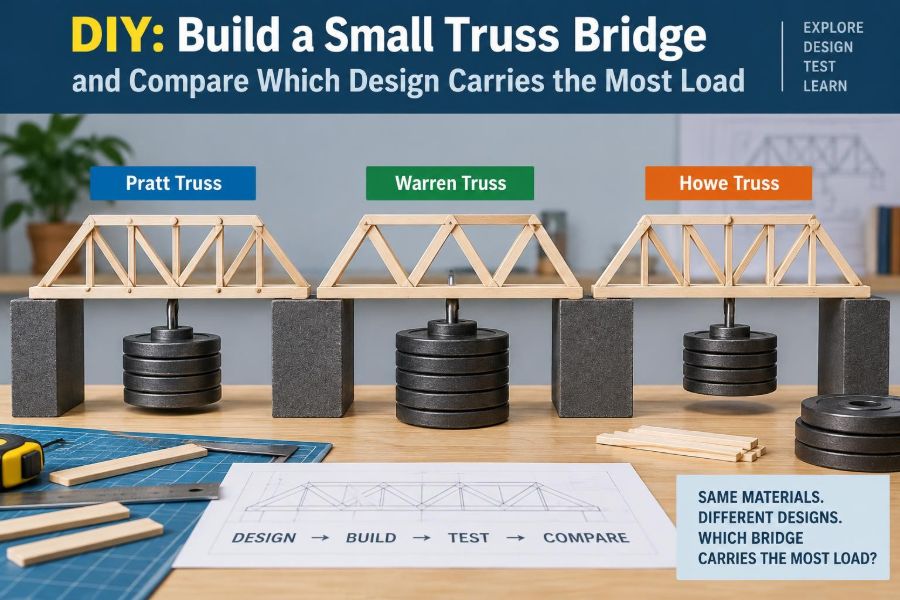

A narrow gap in a classroom, a pile of craft sticks, and one question: which bridge will hold the most weight before it fails? It sounds like a simple challenge, but it quickly becomes a lesson in forces, geometry, materials, and careful construction.
Real bridges do not rely on a single beam simply being “strong enough.” Their shape directs loads along planned paths to supports, while individual members resist tension or compression. A tabletop model makes those hidden actions visible.
Building several small truss bridges is also a useful reminder for working engineers: a good concept can perform poorly when connections are weak, dimensions drift, or the load is introduced in an unexpected place.
This experiment compares common truss layouts fairly, records useful observations, and turns a craft project into a compact structural engineering investigation.
🌉 What This Bridge Challenge Teaches
A truss bridge is a framework of straight, connected members arranged primarily as triangles. Under load, those members ideally carry axial force: either tension, which pulls a member longer, or compression, which pushes it shorter.
Your goal is not simply to produce the strongest single model. It is to compare designs under comparable conditions and explain why one carried more load, deflected less, or failed differently.
🎯 Define a Fair Experimental Question
Start with a focused question: “Which truss geometry carries the greatest central load when span, material quantity, supports, and loading method are held as similar as practical?”
This wording matters. If one bridge is wider, uses twice as many sticks, or has much larger joints, the result may describe those changes rather than the truss pattern itself.
📏 Choose a Manageable Model Scale
A clear span of about 400 to 600 mm works well for typical craft sticks, thin timber strips, or stiff card members. Keep the span identical for every test bridge.
Select one truss depth, such as roughly one-fifth to one-quarter of the span, and retain it across alternatives. A deeper truss usually reduces chord forces for a given load, so changing depth would overwhelm the geometry comparison.
🧰 Gather Consistent Materials
Choose materials that are reasonably uniform. Wooden craft sticks are accessible, but their grain, knots, and slight curvature create variation. Basswood strips can be more consistent, while drinking straws demonstrate instability particularly clearly.
- Enough identical sticks or strips for all specimens
- Wood glue or another adhesive suitable for the chosen material
- Card or thin plywood gusset plates, if used
- A ruler, square, pencil, utility cutter, and cutting mat
- Clamps or clips for joints
- Two level support blocks and a loading platform
- Small known masses, such as unopened food cans or calibrated weights
- A scale and a notebook or spreadsheet
Use eye protection while cutting. Do not load a model above people, glass, electronics, or toes; brittle pieces and weights can fall suddenly.
⚖️ Control the Variables That Matter
In an ideal comparison, only the internal web arrangement changes. Keep the following as constant as possible: span, truss depth, bridge width, member material, number of layers in the top and bottom chords, joint method, curing time, and support spacing.
Perfect equality is rarely achievable in a DIY experiment. Record meaningful differences instead of hiding them. That habit is closer to real test practice than pretending every specimen is identical.
🔺 Why Triangles Form Stable Frameworks
A four-sided frame with pin-like corners can change from a rectangle into a parallelogram without changing member lengths. That shape change is called a mechanism. Add a diagonal, and the rectangle becomes two triangles that resist this racking motion.
Triangles are not magically strong by themselves. Their value is geometric stability: applied loads are converted into forces along straight members rather than relying mainly on flexible bending resistance at the joints.
🧭 Understand the Load Path First
Imagine placing a weight at midspan. The load travels from the loading platform into a joint, through diagonal and vertical web members, into the top and bottom chords, and then to the supports.
A load path should be continuous. A member that stops short of a joint, a poorly aligned lap, or a soft glue connection can interrupt that path and force nearby parts to bend or twist.
↕️ Tension and Compression in a Simply Supported Truss
For a typical simply supported bridge loaded downward near its center, the top chord is commonly in compression and the bottom chord is commonly in tension. The web members transfer shear between them.
Think of a ruler bent downward: its upper fibers shorten while its lower fibers stretch. A truss separates those actions into distinct chords, held apart by web members.
🪵 Compression Is Often the Limiting Case
A tension member generally fails only when its material or connection tears apart. A slender compression member may fail earlier by moving sideways, an instability known as buckling.
That is why the top chord deserves special attention. It may have adequate material strength yet buckle out of plane because it is long, narrow, or poorly braced.
📐 Select Three Useful Truss Designs
Compare three arrangements that use similar overall dimensions. The goal is not to declare one universally best; it is to see how force patterns and construction details affect each form.
| Truss type | Visual pattern | Useful observation focus |
|---|---|---|
| Pratt | Diagonals slope toward the center from the top chord | Many diagonals tend to act mainly in tension under gravity loading |
| Howe | Diagonals slope toward the supports from the top chord | Many diagonals tend to act mainly in compression under gravity loading |
| Warren | Repeated alternating triangles | Forces distribute through a simple, economical triangular pattern |
These descriptions assume ordinary downward loading and conventional orientation. Force signs can change with load position, support conditions, and geometry.
🔷 Build a Pratt Truss Specimen
In a Pratt truss, verticals divide the span into panels and diagonals generally slope down toward the center. Under a central gravity load, its long diagonals are often placed mainly in tension.
This can suit slender members that resist pulling well, while shorter verticals take more compression-related demand. Your model may reveal a different weak point if the joints, chords, or lateral bracing govern first.
🔶 Build a Howe Truss Specimen
The Howe arrangement reverses the diagonal direction relative to a Pratt truss. Under comparable loading, the diagonals commonly experience compression rather than tension.
For lightweight, slender craft-stick diagonals, this can make buckling more likely. That does not make Howe trusses poor engineering; it demonstrates that member material, section size, and bracing must suit the expected force type.
🔻 Build a Warren Truss Specimen
A Warren truss uses a sequence of alternating triangles, often without many verticals. It is visually simple and can use fewer distinct member types, which makes it a good model-building comparison.
Under a point load at a joint, some diagonals may carry significant compression while others carry tension. The exact pattern varies with where the load enters, so consistent loading locations are essential.
🧱 Design the Chords Before the Web
The top and bottom chords run along the full length of the bridge and usually see the largest overall axial forces. Use the same chord arrangement in every specimen, perhaps two laminated sticks with staggered splices if a single stick is too short.
Never place all chord splices at the same location. Staggering them avoids concentrating weakness in one cross-section, especially near the middle where chord force is often greatest.
🔩 Make Joints That Behave Like Joints
Truss calculations often assume ideal pin joints, which rotate freely and transmit no bending moment. Craft-stick connections are neither perfect pins nor perfectly rigid; glue thickness, overlap, and gusset stiffness all influence their behavior.
Use a repeatable joint detail. Ensure each member centerline meets near the intended node, rather than attaching a diagonal several millimeters away and creating an unintended eccentricity that bends the member.
🗂️ Use a Full-Size Template
Draw each truss at full scale on paper, including panel points, chord lines, and diagonals. Cover the drawing with waxed paper or another release layer so the glued bridge does not become part of the template.
A template improves repeatability, keeps panels square where intended, and prevents a common problem: one truss side quietly becoming longer or deeper than the other.
⏳ Let Adhesive Cure Properly
A joint can feel dry long before it has developed its intended strength. Follow the adhesive manufacturer’s curing guidance, and apply the same curing period to every model.
Testing one bridge after a few hours and another after a full day is not a comparison of truss layouts. It is partly a comparison of adhesive condition.
🚧 Build Two Side Trusses, Not One Flat Frame
A bridge needs resistance to sideways movement as well as vertical load. Build two matching truss planes, spaced apart by cross members, to create a narrow box-like structure.
Without lateral bracing, the compressed top chords may roll sideways and buckle out of the truss plane. This is a structural failure, not merely an untidy model.
🔗 Add Lateral and Cross Bracing
Connect the two side trusses at several panel points. Add diagonal cross-bracing across the top plane where practical, particularly in regions of compression.
Keep this bracing consistent across models. If one design receives extensive cross-bracing and another remains open, the test is comparing whole systems with different stability provisions, not just web geometry.
🪜 Prepare Realistic Simple Supports
Rest the bridge ends on two level blocks with a clear gap between them. Avoid gluing the model to its supports unless that fixed-end condition is deliberately part of every test.
Simple supports allow end rotation and usually permit horizontal movement at one end. For a small model, smooth bearing surfaces and careful placement approximate this behavior sufficiently for a comparative exercise.
🎯 Apply the Load at a Joint
Place load at a panel point, ideally the central bottom-chord joint, using a small platform that bears equally on both side trusses. This encourages the structure to act as a truss.
Loading the middle of a chord between joints introduces local bending that the ideal truss model does not represent. It can still be a useful separate experiment, but do not confuse it with a joint-loaded comparison.
🧪 Establish a Safe Loading Sequence
Add known mass in small, repeatable increments. Pause after each increment to observe deflection, listen for cracking, and confirm that the loading platform remains centered.
- Measure the unloaded bridge depth and note any initial twist.
- Add one increment of mass at the chosen loading point.
- Record total applied mass, midspan deflection, and visible changes.
- Continue until a clearly defined failure criterion occurs.
- Remove loose pieces only after all weight has been safely taken off.
Do not lean over the bridge during the final increments. A model rarely gives a dramatic warning before a brittle glue joint or buckled chord releases.
📊 Decide What Counts as Failure
Failure need not mean complete collapse. Define it before testing. Possible criteria include a broken member, a separated joint, permanent buckling, a specified deflection limit, or inability to carry the next load increment.
For educational comparisons, record both the first damage load and the maximum sustained load. First damage often reveals the governing weakness more clearly than the final, messy collapse.
📝 Record More Than the Final Weight
A bridge that carries the highest load is interesting, but the test observations explain its behavior. Create a log for each specimen with construction notes and test results.
- Truss type, span, depth, width, and bridge mass
- Chord and web member arrangement
- Load increments and estimated total load
- Midspan deflection at each increment
- First crack, first visible buckle, or first joint rotation
- Location and mode of final failure
Photographs taken from the same angle before and after loading can be valuable, especially when comparing lateral buckling or support movement.
📉 Compare Strength, Stiffness, and Efficiency
Strength is the maximum load carried before your chosen failure criterion. Stiffness is resistance to deflection: a stiffer bridge bends less under the same load. These are related but not identical properties.
For models with different self-weights, calculate a simple efficiency indicator: maximum supported load divided by bridge mass. Treat it as a classroom comparison, not a universal engineering rating, because test setup and material variation strongly influence it.
🔍 Read the Failure Mode Like Evidence
A snapped bottom chord suggests excessive tension or a weak splice. A bowed top chord suggests compression buckling. A joint peeling apart may point to insufficient overlap, poor surface preparation, or force entering the joint off-center.
If the whole bridge twists, inspect cross-bracing, unequal side-truss geometry, and whether the load was centered. The first failure is often the most informative clue; secondary breaks can follow rapidly.
🧠 Predict Forces Before You Test
Before adding weights, sketch each bridge and mark your prediction: which chord is in tension, which is in compression, and which web members look most vulnerable. After testing, compare prediction with observation.
For a more advanced step, treat the nodes as ideal pins and use equilibrium. At each joint, the horizontal and vertical forces should balance. This method of joints is most reliable when loads are applied at nodes and member self-weight is small relative to the test load.
📌 Why the “Best” Design May Not Win
A Pratt model may be theoretically attractive with slender tension diagonals, yet lose because its top chord is underbuilt. A Warren model may win because its construction is more symmetrical and its joints happened to be better aligned.
That is not a failed experiment. It shows that structural performance belongs to the complete system: geometry, member size, connections, bracing, fabrication quality, supports, and loading all matter.
⚠️ Avoid Common Testing Mistakes
Several errors can make a result misleading. Most are preventable with a template, a written test plan, and patient setup.
- Changing both truss pattern and material quantity at once
- Testing bridges with different spans or support positions
- Applying a load off-center or onto only one side truss
- Using unequal adhesive curing times
- Ignoring bridge mass when calling a design “efficient”
- Reporting only collapse load and not the failure location
- Assuming a broken glue joint proves the truss geometry was weak
🔄 Improve One Feature at a Time
After the first round, redesign the weakest feature while changing as little else as possible. If top-chord buckling governed, add lateral restraint or increase chord thickness. If joints failed, improve gussets or overlap length.
One-variable iterations teach more than rebuilding everything at once. They allow you to connect a measured improvement with a plausible structural reason.
🏗️ Connect the Model to Full-Scale Bridges
Full-scale bridge design involves effects that a small model only approximates: wind, fatigue from repeated traffic, temperature movement, foundations, corrosion, construction sequence, code requirements, and detailed connection behavior.
Scale also changes behavior. Glue joints do not scale like bolted or welded steel connections, and wood grain can dominate a tiny member. The model is therefore a demonstration of principles, not a direct design method for a real bridge.
👥 Turn It Into a Useful Team Exercise
Assign roles if several people are involved: design lead, fabrication lead, quality checker, loading operator, and recorder. Require each team to submit a prediction before testing and a brief failure explanation afterward.
Comparing notes is more valuable than ranking bridges alone. A team that identifies an uncontrolled variable has produced sound engineering judgment, even if its bridge did not carry the largest load.
✅ The Core Structural Takeaway
A truss works by giving forces intentional routes through triangles, chords, and connections. Its geometry can reduce bending in individual members, but it cannot compensate for an unstable compression chord, a weak joint, or an uncontrolled test condition.
The most meaningful outcome is not simply a winning pattern. It is the ability to explain how load moved through the bridge, what failed first, and what specific change would make the next version perform better.
Build consistently, load carefully, and let each failure reveal the force path that your bridge was unable to carry. That is the practical habit behind better models and better structures. 🏗️🔺📏