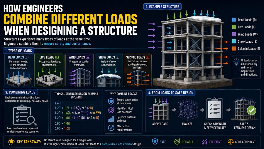

A building, bridge, tower, stadium, or industrial structure is rarely subjected to only one type of force at a time. A roof may carry its own weight while also supporting people, equipment, snow, and wind pressure. A bridge may simultaneously experience the weight of the structure, moving vehicles, temperature changes, braking forces, and gusts of wind.
Structural engineers therefore cannot design a structure by checking each load independently and assuming the worst effects simply add together. Instead, they use carefully defined load combinations to represent realistic but sufficiently severe conditions that a structure may experience during its life. 🏢⚖️
Load combinations are fundamental to structural engineering because they allow engineers to determine whether beams, columns, foundations, connections, and other components have adequate strength, stability, and serviceability under many possible loading scenarios.
The process combines structural mechanics, probability, safety factors, and requirements established by engineering design standards.
⚙️ What Is a Structural Load?
A load is any force, weight, pressure, acceleration, or imposed effect that creates stress or deformation in a structure.
Some loads are present almost all the time. Others occur only occasionally.
Common structural loads include:
- 🧱 Dead loads
- 👥 Live loads
- 🌬️ Wind loads
- 🌨️ Snow loads
- 🌎 Earthquake loads
- 🌡️ Thermal effects
- 🌧️ Rain loads
- 🚗 Vehicle loads
- 🏭 Equipment and machinery loads
Each type behaves differently, which is why engineers must understand both its magnitude and likelihood.
🧱 Dead Load: The Structure’s Permanent Weight
Dead load is the permanent weight of the structure and permanently attached components.
Examples include:
- Beams
- Columns
- Concrete slabs
- Walls
- Roofing
- Fixed mechanical systems
- Permanent finishes
If a concrete floor slab has a known thickness and density, its self-weight can be calculated relatively accurately.
Dead load is usually among the most predictable structural loads because the materials and dimensions are known during design.
For this reason, its uncertainty is often lower than that of more variable loads such as occupancy or weather.
👥 Live Load: Loads That Change With Use
Live load represents movable or temporary loads caused by how a building or structure is used.
Examples include:
- People
- Furniture
- Storage
- Movable equipment
- Temporary materials
A library floor may require a greater live-load capacity than a residential bedroom because bookshelves can create much heavier floor loading.
Engineers obtain minimum design live loads from applicable structural codes.
Actual live load changes over time, so it is treated statistically rather than as a perfectly known quantity.
🌬️ Wind Load
Wind creates pressure and suction on buildings and other structures.
Depending on wind direction and building geometry, it can cause:
- Lateral forces
- Roof uplift
- Overturning moments
- Torsion
- Cladding pressures
Tall buildings can experience especially significant wind effects.
Wind load depends on factors such as:
- Basic wind speed
- Building height
- Terrain
- Exposure
- Shape
- Importance of the structure
Engineers often evaluate wind from multiple directions because the most critical force in one structural element may occur under a different wind direction from another.
🌎 Earthquake Load
Earthquake loading is different from ordinary static loading.
During an earthquake, the ground accelerates, causing the mass of a structure to generate inertial forces.
These forces can act in multiple directions and can produce:
- Horizontal shear
- Overturning
- Torsion
- Vertical acceleration
- Repeated cyclic deformation
Seismic design is especially concerned with preventing catastrophic collapse.
Structures in high-seismic regions may therefore be designed to undergo controlled inelastic deformation while maintaining overall stability.
🌨️ Snow and Rain Loads
Roofs may accumulate snow, rainwater, or both.
Snow load depends on factors such as:
- Geographic location
- Roof slope
- Wind exposure
- Roof temperature
- Drifting
- Adjacent roof heights
Snow can accumulate unevenly, particularly near parapets or higher portions of a building.
Rain can also create significant loading if roof drainage becomes blocked.
Engineers therefore check roof systems for these environmental effects.
🏭 Equipment and Dynamic Loads
Industrial structures often support heavy machines.
Equipment may produce both static weight and dynamic effects such as vibration or rotating imbalance.
Examples include:
- Turbines
- Pumps
- Compressors
- Cranes
- Generators
- Conveyor systems
A machine weighing 20 tonnes may create forces much greater than its static weight if vibration or impact is significant.
Dynamic analysis may therefore be necessary.
🧮 Why Engineers Use Load Combinations
It might seem safest to simply add the maximum possible dead, live, snow, wind, earthquake, and equipment loads together.
However, this is usually unrealistic.
The probability that every variable load reaches its maximum value at exactly the same moment is extremely small.
For example, a building may be unlikely to experience:
Maximum occupancy + maximum snow + maximum wind + maximum earthquake
all at precisely the same time.
Design standards therefore define load combinations that represent credible severe conditions.
The dominant load is often taken near its full design value, while accompanying variable loads may be reduced.
This creates safe but economically reasonable designs.
⚖️ What Are Load Factors?
Load combinations usually apply numerical multipliers called load factors.
A simplified conceptual combination might look like:
1.2D + 1.6L
where:
- D = dead load
- L = live load
- 1.2 and 1.6 = load factors
These factors account for uncertainty and provide a margin of safety.
Variable loads often receive larger factors because they are less predictable.
Exact combinations and factors depend on the structural design code, material standard, design method, building category, and jurisdiction.
Engineers must use the requirements applicable to the specific project.
🛡️ Strength Design and Ultimate Limit States
One major design goal is preventing structural failure.
This is often checked using strength design or ultimate limit state design.
The engineer applies factored load combinations to determine the maximum forces a structural member might need to resist.
These internal forces can include:
- Bending moment
- Shear
- Axial force
- Torsion
The calculated demand is then compared with the design resistance of the structural member.
Conceptually:
Design resistance ≥ Required structural demand
If the demand exceeds capacity, the member must be strengthened, enlarged, reinforced, or redesigned.
📏 Serviceability Limit States
A structure can remain standing yet still perform poorly.
For example, a floor might deflect enough to crack finishes or feel uncomfortable to occupants.
A tall building might sway excessively in moderate wind.
These are serviceability problems.
Serviceability checks may consider:
- Deflection
- Vibration
- Cracking
- Settlement
- Drift
- Occupant comfort
Serviceability load combinations are often less heavily factored than strength combinations because they represent normal operating conditions rather than near-failure scenarios.
🏢 Example: Designing a Floor Beam
Imagine a beam supporting a building floor.
The beam experiences:
- Dead load from the slab and finishes
- Live load from occupants and furniture
Suppose:
Dead load = 10 kN/m
Live load = 8 kN/m
A simplified strength load combination might be:
1.2D + 1.6L
Substituting the loads:
1.2 × 10 + 1.6 × 8
= 12 + 12.8
= 24.8 kN/m
The engineer then analyzes the beam under this factored load.
The resulting bending moment and shear are compared with the beam’s design capacity.
This process ensures that uncertainty in both loading and material resistance is appropriately addressed.
🌬️ Example With Wind
Now imagine the same building must also resist wind.
A simplified conceptual combination might include:
Dead load + reduced live load + wind
Why might live load be reduced?
Because the probability of maximum occupancy occurring at exactly the same time as the design-level wind event may be lower than the probability of either event independently.
Design standards account for this through combination factors.
The engineer checks multiple combinations because one may govern beam design while another governs columns, foundations, or connections.
🌎 Earthquake Load Combinations
Earthquake combinations often require special treatment.
Seismic forces can act in different directions, and engineers may need to combine horizontal components.
Gravity loads are also present during an earthquake.
A structural column may therefore experience:
Dead load + part of live load + seismic force
Depending on the structural system, earthquake effects may reverse direction.
Engineers must therefore check both positive and negative seismic actions.
This is especially important for bracing, moment frames, shear walls, and foundations.
↔️ Loads Can Act in Opposite Directions
Some loads do not merely add together.
They may oppose one another.
For example, wind uplift on a roof can act upward while dead load acts downward.
In this case, the engineer may need to check whether the upward wind force exceeds the stabilizing weight of the roof.
This can govern the design of:
- Roof connections
- Anchor bolts
- Hold-down systems
- Foundation ties
A light structure may actually be more vulnerable to wind uplift than a heavier one.
🔄 Multiple Load Cases
Engineers usually create many load cases before combining them.
A load case represents one defined loading condition.
Examples might include:
- Dead load
- Floor live load
- Roof live load
- Wind from north
- Wind from south
- Wind from east
- Wind from west
- Earthquake in X direction
- Earthquake in Y direction
- Snow load
Structural analysis software can combine these automatically according to code-defined equations.
Each member may be governed by a different combination.
📊 The Governing Load Combination
The governing load combination is the combination producing the most critical demand for a particular design check.
For example:
- One combination may create maximum bending.
- Another may create maximum shear.
- Another may create maximum compression.
- Another may create maximum uplift.
Therefore, engineers cannot simply identify one “worst” combination for the entire building.
Every important structural component and failure mode must be checked.
🧠 Why Probability Matters
Modern load combinations are partly based on statistical reasoning.
Dead load is relatively predictable.
Maximum snow load is less frequent.
Extreme wind is rarer still.
Major earthquakes may have very low annual probabilities.
Design codes use reliability concepts to create combinations that produce appropriate safety levels without assuming impossible simultaneous extremes.
This helps balance two competing goals:
Safety 🛡️ and economy 💰
If structures were designed for every conceivable maximum load occurring simultaneously, they could become unnecessarily massive and expensive.
🏗️ Load Paths Matter
Combining loads correctly is only part of the job.
Engineers must also understand how forces travel through the structure.
This is called the load path.
For a simple building:
Roof → Beams → Columns → Foundations → Soil
Wind might follow a different path:
Exterior wall → Diaphragm → Shear wall or frame → Foundation
A complete load path ensures that every force has a continuous route to the ground.
Missing or weak connections can cause failure even when individual beams and columns appear adequate.
🔩 Connections Must Resist Combined Loads
Structural connections often experience several force types simultaneously.
A steel connection may resist:
- Shear
- Tension
- Compression
- Moment
Likewise, anchor bolts may experience both tension and shear.
Engineers must evaluate these interactions.
A connection that is safe under pure tension may have reduced capacity when significant shear is present at the same time.
Material design standards provide interaction equations for these combined effects.
🧱 Columns and Combined Axial Load Plus Bending
Columns commonly experience both compression and bending.
Gravity loads create axial compression.
Wind or earthquake loading can introduce lateral bending.
The engineer must therefore consider the interaction between:
Axial force + bending moment
A heavily compressed column may have less remaining capacity for bending.
Interaction diagrams or code equations help engineers determine whether the combined demand is acceptable.
🏢 Foundation Load Combinations
Foundations must support forces from the entire structure.
Possible effects include:
- Vertical compression
- Uplift
- Horizontal shear
- Overturning moment
Different load combinations may govern different foundation checks.
For example:
A gravity-dominated combination may control soil bearing pressure.
A wind combination may control overturning.
An uplift combination may control anchor design.
Earthquake loading may control lateral resistance.
Foundation design therefore requires the same systematic load-combination approach as the structure above.
🌡️ Temperature Effects
Structures expand when heated and contract when cooled.
If movement is restrained, temperature changes can generate significant internal forces.
Long bridges, pipelines, and industrial structures can be particularly sensitive.
Engineers may use:
- Expansion joints
- Sliding bearings
- Flexible connections
to accommodate thermal movement.
Where movement is restrained, thermal effects may need to be included in load combinations.
🏗️ Construction Loads
A structure can experience important loads before it is completed.
During construction, certain beams may temporarily support materials or equipment they will never carry once the building is finished.
Temporary bracing may also be required before the full structural system becomes active.
Engineers therefore evaluate construction-stage load combinations.
These may include:
- Stored materials
- Concrete placement loads
- Construction equipment
- Workers
- Temporary wind exposure
Construction conditions can sometimes be more critical than final-service conditions.
🌉 Bridge Load Combinations
Bridge design introduces additional loading effects.
A bridge may experience:
- Self-weight
- Vehicle loads
- Pedestrian loads
- Braking forces
- Wind
- Thermal expansion
- Water pressure
- Earthquake forces
Moving vehicles also create dynamic amplification.
Engineers analyze numerous load positions to determine where vehicle loading causes maximum structural effects.
Software can move simulated axle loads across the bridge and automatically identify critical cases.
💻 Structural Analysis Software
Modern engineering software can evaluate thousands of combinations very quickly.
The engineer first defines:
- Structural geometry
- Material properties
- Supports
- Load cases
- Load combinations
The program then calculates internal forces and deformations.
However, software does not replace engineering judgment.
Incorrect loads or unrealistic assumptions can produce precise-looking but incorrect results.
Engineers must still verify:
- Whether the model represents the real structure
- Whether load paths are correct
- Whether the appropriate combinations were used
- Whether results make physical sense
📐 Load Combinations and Building Codes
Structural codes provide standardized rules for load combinations.
These rules vary depending on country and design philosophy.
Examples of widely used structural standards include frameworks based on:
- Strength design
- Load and Resistance Factor Design
- Limit State Design
- Allowable Stress Design
Different jurisdictions may use different equations and terminology.
Therefore, engineers must not casually transfer a load combination from one code into another project.
The governing standard must always be verified.
🛡️ Load Factors vs. Resistance Factors
Modern structural design often uses safety adjustments on both sides of the equation.
Loads may be multiplied by load factors.
Material resistance may be reduced by resistance factors or partial safety factors.
Conceptually:
Factored load effect ≤ Reduced design resistance
This accounts for uncertainty in both:
- What loads the structure will experience
- How strong the structure actually is
Concrete strength, steel yield strength, construction tolerances, and model assumptions all contain uncertainty.
📉 Load Reduction
Certain codes allow some live loads to be reduced for structural elements supporting large areas.
Why?
It is statistically unlikely that every part of a very large floor area will carry the maximum specified live load simultaneously.
A column supporting several floors may therefore qualify for a calculated live-load reduction.
However, special occupancies and certain heavy-use areas may have restrictions.
The rules depend on the applicable design standard.
🔍 Influence Areas and Tributary Areas
Engineers often use tributary areas to determine how much load is assigned to a beam, column, or foundation.
A floor slab distributes its load to surrounding beams.
Those beams transfer loads to columns.
Columns transfer them to foundations.
If a beam supports a 3-meter-wide tributary strip of floor carrying 5 kPa:
Line load = 5 kN/m² × 3 m = 15 kN/m
This simplifies the transfer of area loads into member loads.
⚠️ Accidental and Exceptional Loads
Some structures must be designed for unusual events.
These can include:
- Vehicle impact
- Blast effects
- Fire
- Accidental internal pressure
- Progressive collapse scenarios
These loads are often treated through special or accidental load combinations.
The goal may not be to keep the structure completely undamaged.
Instead, the requirement may be to prevent disproportionate or catastrophic collapse.
🔥 Fire Load Combinations
During a severe fire, structural materials lose strength.
Steel can soften significantly as temperature rises, while concrete can experience cracking and spalling.
Fire design may therefore use special combinations that assume reduced probabilities of other extreme loads occurring simultaneously.
The engineer evaluates whether the structure can maintain sufficient stability for the required fire-resistance period.
🧮 Load Envelopes
When many combinations are analyzed, engineers often create a load envelope.
A load envelope records the maximum and minimum response across all relevant cases.
For a beam, the envelope may show:
- Maximum positive bending moment
- Maximum negative bending moment
- Maximum shear
- Maximum deflection
This makes it easier to identify critical design demands without manually reviewing every combination.
🏙️ Tall Buildings and Combined Effects
Tall buildings are especially sensitive to complex load combinations.
Gravity loads may create enormous column forces, while wind produces lateral sway and overturning.
Second-order effects can further increase demands.
These effects occur because axial loads act through a structure that has already displaced laterally.
Engineers often refer to this as P-Delta behavior.
Advanced analysis may therefore include:
- Nonlinear geometry
- Dynamic wind response
- Seismic response
- Staged construction
- Foundation interaction
Load combinations become part of a much broader structural-analysis framework.
🌉 Why Different Members Have Different Critical Loads
A structural component that looks heavily loaded under one condition may not be critical under another.
For example:
- Gravity may control a floor beam.
- Wind may control a perimeter column.
- Earthquake may control a shear wall.
- Uplift may control a roof connection.
- Overturning may control a foundation.
This is why structural design is an iterative process.
Engineers repeatedly analyze, size, check, and revise the structure until every important component satisfies its required criteria.
🧠 Engineering Judgment Remains Essential
Building codes provide equations, but they cannot anticipate every real-world situation.
Engineers must understand what the equations represent.
They may need to consider unusual conditions such as:
- Heavy equipment added later
- Temporary storage loads
- Irregular building geometry
- Nearby excavation
- Extreme local weather
- Equipment vibration
- Changes in occupancy
A mathematically correct combination can still be inadequate if the engineer has omitted an important real load.
🛡️ Why Load Combinations Improve Safety
The purpose of load combinations is not to predict one exact future event.
No engineer can know precisely how many people will occupy a building during a particular windstorm decades from now.
Instead, load combinations create a rational framework for designing against a range of realistic severe scenarios.
They allow structural engineers to manage uncertainty while maintaining consistent safety levels.
This approach has helped make modern buildings and infrastructure remarkably reliable. 🏗️✅
✨ Conclusion
Engineers combine different structural loads because buildings, bridges, towers, and other structures experience many forces at the same time.
Permanent dead loads act continuously, while variable loads such as occupancy, wind, snow, earthquakes, equipment, and temperature effects occur with different magnitudes and probabilities.
Rather than simply adding every maximum load together, engineers use standardized load combinations. These combinations apply factors and reduction rules that reflect uncertainty and the likelihood of different loads occurring simultaneously.
The structure is then checked under many possible scenarios.
One combination may govern bending in a beam, another may govern compression in a column, and another may control uplift or overturning at the foundation.
Engineers also evaluate both strength and serviceability, ensuring that a structure not only avoids collapse but also limits excessive deflection, vibration, cracking, and movement.
Modern structural software can process thousands of combinations quickly, but the engineer must still understand the load path, applicable codes, material behavior, and physical meaning of the results.
Ultimately, structural load combinations are a carefully engineered way of asking:
“What demanding combinations of forces could this structure realistically experience, and can every part of it safely resist them?” 🏗️⚖️
By answering that question systematically, engineers create structures that are safe, durable, economical, and capable of performing reliably throughout their intended lives.