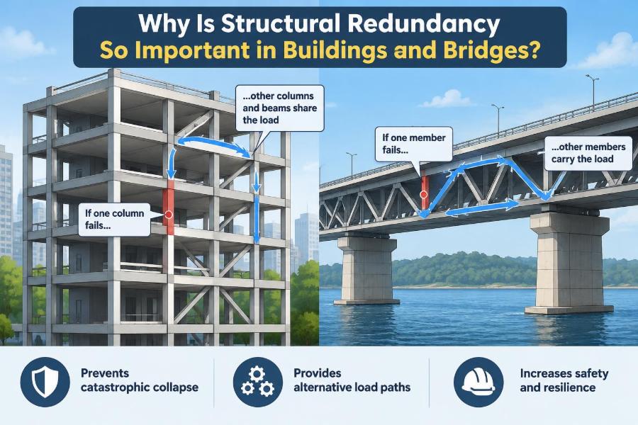

A bridge carries traffic every day with little drama. A building floor supports people, furniture, equipment, and changing layouts without anyone seeing the load paths at work. That apparent simplicity is usually the result of many deliberate engineering decisions.
But what happens when one connection corrodes, one brace is damaged, a column is struck, or a construction error weakens a local component? A structure that depends completely on one element can lose far more than that one element.
Structural redundancy is the reason many well-designed systems can redirect forces, limit local damage, and remain standing long enough for people to escape or for engineers to intervene. It does not mean that a structure is indestructible. It means it has alternatives.
For students, redundancy is a key idea linking structural analysis to real safety. For practicing engineers, it is a design habit: asking not only whether the structure works in normal conditions, but also what happens when part of it no longer works as intended.
🧩 Structural Redundancy Defined
Structural redundancy is the presence of multiple possible load paths or reserve mechanisms within a structure. If one member, connection, or support loses capacity, other parts can take on some of the load.
A load path is the route by which force travels through a structure to the ground. For gravity loads, the route may run from a floor slab to beams, columns, foundations, and soil. For wind or earthquake forces, it may run through diaphragms, frames, walls, bracing, and foundations.
Redundancy exists when that route is not uniquely dependent on one component. The remaining system must still have enough strength, stiffness, continuity, and ductility to respond safely after damage.
🧠 Why “More Material” Is Not the Same Thing
Adding a larger beam or thicker wall can increase strength, but it does not automatically create redundancy. A single very strong hanger supporting a canopy remains a single point of failure if no alternate support is available.
Conversely, several connected elements may create redundancy without simply duplicating material. A continuous beam over several supports can redistribute bending after one span is affected, while a set of independent simply supported beams cannot readily help one another.
Redundancy is therefore about system behavior, not just member size. Capacity matters, but connectivity and the ability to develop alternate action matter too.
🛣️ The Everyday Detour Analogy
A road network makes the idea intuitive. If one street closes and there is only one way to reach a destination, travel stops. If nearby streets connect to the same destination, drivers can detour, although congestion may increase.
A redundant structure behaves similarly. When one path is interrupted, forces seek available connected paths. Those paths may experience higher demands, just as detour roads experience heavier traffic.
The analogy has a limit: structural redistribution is governed by stiffness, strength, geometry, and deformation compatibility. Forces do not “choose” routes intelligently; they follow the physical response of the connected system.
⚖️ Strength, Stiffness, and Ductility
Redundancy depends on more than ultimate strength. Stiffness controls how load is shared before damage, while ductility describes a component’s ability to deform substantially without sudden loss of resistance.
If a member fails in a brittle way, it may lose capacity too quickly for surrounding elements to engage. If connections and members can deform in a controlled manner, forces have more opportunity to redistribute.
This is why a redundant layout made of brittle, poorly detailed components may still be vulnerable. A robust system needs credible post-damage behavior, not merely multiple lines on a framing plan.
🔗 Load Paths Must Be Continuous
Every alternate path must be connected from the point of damage to a reliable support or foundation. A secondary beam cannot help if its connection fails before it can transfer significant force.
Engineers therefore examine joints, anchors, reinforcement development, welds, bolts, diaphragms, collectors, and foundations. A strong member attached through a weak or discontinuous detail may provide little practical redundancy.
Continuity is particularly important at changes in level, transfer structures, building corners, expansion joints, and interfaces between materials. These are places where the assumed load path can be interrupted.
🏢 Redundancy in Building Gravity Systems
Building floors often use grids of beams, slabs, girders, and columns. A two-way reinforced concrete slab, for example, can distribute gravity load in more than one direction when it is properly supported and detailed.
Framed systems may also share load through continuous beams and adjacent bays. If one member is damaged, neighboring framing can sometimes bridge around the affected area, subject to the magnitude and location of the damage.
That capability should not be assumed casually. Long-span floors, large openings, deep transfer girders, and irregular column arrangements can concentrate loads and reduce the number of realistic alternatives.
🌉 Redundancy in Bridge Systems
Bridge redundancy is especially visible because bridge elements are often exposed to weather, vehicle impact, fatigue loading, and inspection constraints. Multiple girders under a deck can provide alternatives that a single-girder arrangement does not possess.
A deck can distribute wheel loads transversely among girders, but the extent of distribution depends on deck stiffness, diaphragms, cross-frames, connections, and girder geometry. It is not enough to count girders.
Continuous spans may offer alternate load paths across supports, while simple spans act more independently. Both approaches can be appropriate, but their response to localized damage differs.
🏗️ Frames, Walls, and Braces Share Lateral Loads
Buildings must resist lateral forces from wind and, in many regions, earthquakes. Common lateral-force-resisting systems include moment frames, braced frames, and shear walls.
When several lines of resistance work together, one line may carry more load if another is impaired. However, differences in stiffness can make one wall or frame attract much more force than its neighbors during normal loading.
Good redundancy does not mean every element receives equal force. It means the system has a sensible, connected, and analyzable ability to redistribute force when conditions change.
🧱 The Role of Diaphragms
Floors and roofs often act as diaphragms: horizontal structural elements that collect and distribute lateral loads to frames or walls. Concrete slabs, steel decks with appropriate attachments, and timber diaphragms can serve this role.
A diaphragm is central to redundancy because it links vertical lateral-resisting elements. If it is flexible, discontinuous, heavily perforated, or poorly connected, walls and frames may not share load as expected.
Large openings for stairs, atriums, service shafts, and mechanical equipment deserve careful attention. They can force load around the opening and increase demand on collectors and boundary elements.
📐 Indeterminacy Creates Opportunity for Redistribution
Engineers call a structure statically indeterminate when equilibrium equations alone cannot determine all its reactions and internal forces. Additional compatibility and stiffness relationships are needed.
Indeterminacy often provides the mathematical basis for redistribution. A continuous beam over multiple supports, for instance, can shift internal forces when support conditions or member stiffness change.
Yet indeterminacy is not a synonym for safety. It can also create restraint forces from temperature change, shrinkage, settlement, or construction sequence. The designer must understand both the benefits and the demands it introduces.
💥 Local Damage Can Trigger Progressive Collapse
Progressive collapse is a disproportionate spread of failure following an initial local event. The initiating event might be impact, an explosion, severe corrosion, a construction mistake, or another unusual condition.
The concern is not that every local failure must be prevented under every imaginable event. Rather, the system should avoid turning a limited loss into the collapse of a much larger area when practical and appropriate for the structure.
Redundancy helps by offering alternative routes around missing support. It also helps by slowing the sequence of failure, which can be crucial for evacuation and emergency response.
🧮 Alternate-Path Thinking
An alternate-path check asks a direct question: if a selected column, wall segment, hanger, or other critical component were lost, where would the load go next?
The answer may involve beam action, arching action, membrane action in slabs, catenary action in ties, or redistribution through neighboring frames. Each mechanism requires deformation, connection capacity, and compatible geometry.
These checks are not simple exercises in deleting an element from a computer model. The model must represent realistic supports, nonlinear behavior where relevant, connection behavior, and the load combinations appropriate to the intended assessment.
🪢 Ties Can Hold a System Together
Structural ties are continuous tension connections that help components remain linked after local damage. In reinforced concrete, properly continuous reinforcement can support tensile force across regions that would otherwise separate.
In steel and precast construction, connection detailing can provide tie force paths through floors, roofs, and vertical elements. The goal is often to prevent isolated pieces from pulling apart or falling away.
Ties are valuable, but they are not magic cables added at the end of design. Their anchorage, continuity, ductility, corrosion protection, and connection to the larger system determine whether they can develop the intended action.
🧲 Catenary Action Has Conditions
When a beam or slab undergoes large downward deflection after losing a support, it may begin to resist load partly through tension, much like a cable. This is called catenary action.
It can provide substantial reserve resistance in some systems, but only after significant deformation. That deformation may damage finishes, services, partitions, and connections, and it may be unacceptable for ordinary service conditions.
Most importantly, catenary action demands robust end connections and a continuous tension path. Assuming it without verifying those conditions can produce a dangerously optimistic assessment.
🧱 Arching and Membrane Action in Slabs
Slabs can develop behavior beyond simple bending. Compression arching may occur when lateral restraint allows compressive forces to form, while tensile membrane action can develop at larger deflections through reinforcement continuity.
These mechanisms are highly dependent on boundary restraint, cracking, reinforcement detailing, support movement, and geometry. They should be evaluated using methods suitable for the project rather than treated as automatic hidden capacity.
For designers, the lesson is practical: a floor system is often more complex and potentially more resilient than a line of isolated strips, but only if the complete slab-and-support system is properly detailed.
🚧 Connections Are Frequent Weak Links
Members are visible on drawings, but connections determine whether forces can move from one member to another. A redundant conceptual layout can become nonredundant in reality if a connection fractures, slips excessively, tears out, or lacks rotation capacity.
Bolted joints, welded details, reinforcing bar laps, embedded plates, anchors, and bearing regions all deserve attention. Fatigue, corrosion, fabrication tolerances, and erection sequence may affect them over time.
A useful review question is: does the connection have at least the capacity and deformation ability required by the alternate load path? If not, the path is theoretical rather than dependable.
🧯 Ductile Failure Gives Warning and Time
Ductile behavior generally allows visible deformation and gradual energy absorption before complete loss of capacity. Brittle behavior may involve abrupt fracture, crushing, shear failure, or connection rupture with little opportunity for redistribution.
Designers seek ductility through proportioning, confinement, reinforcement detailing, member compactness, stable bracing, and connection design appropriate to the material and loading. The exact methods vary among steel, concrete, timber, and masonry.
Ductility cannot eliminate damage, but it can change the sequence of events. A slower, more stable response often allows neighboring components to engage and reduces the chance of a sudden system-wide outcome.
🌍 Earthquakes Reveal System-Level Behavior
Earthquake loading reverses direction, repeats in cycles, and can impose large deformations. It tests not only the strength of individual members but also the continuity of the entire load path.
Redundant lateral systems can distribute demand among multiple frames or walls, but irregular layouts can produce torsion, concentration of drift, and unexpected demand on particular elements. A building with many walls on one side and few on the other may not respond as its plan suggests.
Seismic design also relies heavily on ductile detailing. The intended yielding locations and protected components must be chosen so that the system dissipates energy without losing its essential gravity-load support.
🌬️ Wind Design Also Benefits from Alternatives
Wind is often thought of as a smooth lateral push, but real wind effects can vary across height and produce dynamic response. Cladding, diaphragms, collectors, frames, walls, and foundations all participate in the force path.
Multiple lateral-resisting lines can improve resilience to a local issue, such as damage to one component or unexpected stiffness change. Still, wind design must consider serviceability as well as strength: excessive drift, vibration, or facade movement can cause problems before structural failure is near.
Redundancy should therefore be balanced with a clear stiffness strategy. A system that is highly redundant but too flexible may not meet functional requirements.
🌊 Foundations and Soil Are Part of the System
Load redistribution eventually reaches the foundations and the ground. If a building shifts extra load to adjacent columns after a local event, their footings, piles, caps, and supporting soil must be able to tolerate the changed demand.
Differential settlement can also alter force distribution in indeterminate structures. A continuous system may bridge minor movement, but restraint forces and cracking can grow when movements exceed assumptions.
Foundation redundancy can include multiple load-transfer elements, interconnected caps or grade beams where appropriate, and careful attention to geotechnical variability. It must be designed with the superstructure, not appended afterward.
🔍 Inspection Keeps Redundancy Real
Redundancy can deteriorate. Corrosion may thin a steel section, water infiltration can damage connections, fatigue can affect details under repeated loading, and unrecorded alterations can remove load-bearing elements.
Inspection and maintenance preserve the alternate paths assumed in design. For bridges, access to bearings, drainage, deck joints, and steel details is particularly important. For buildings, inspections should consider concealed conditions as well as obvious cracks or damage.
Monitoring does not replace sound design, but it can identify changes before several layers of protection are compromised. A redundant system is strongest when its components remain serviceable.
🔨 Construction Sequence Can Change the Load Path
During construction, a partially completed structure may have far less redundancy than the finished building or bridge. Temporary supports, bracing, shoring, and erection stability can control safety during this phase.
Removing shores too early, altering a planned sequence, or loading a young concrete slab before it has achieved the assumed properties can change forces significantly. A final analysis model may not represent these temporary conditions.
Design communication should make critical sequences clear. Contractors and engineers need a shared understanding of what provides stability at every stage, not only after the last connection is complete.
🛠️ Renovations Can Quietly Remove Resilience
Open-plan renovations, new penetrations, heavier equipment, facade replacements, and changes in occupancy can all alter structural behavior. Removing a wall that appears architectural may affect diaphragm action, gravity support, or lateral stiffness.
Likewise, drilling through a beam or slab for new services can cut reinforcement, reduce section capacity, or weaken a critical connection zone. The damage may be hidden once finishes are restored.
Before modifying a structure, verify the original load path and the role of the affected components. A review by a qualified structural professional is especially important where load-bearing elements, lateral systems, or fire-damaged areas are involved.
📊 Common Forms of Redundancy
Different forms of redundancy solve different problems. A structure may have one type while lacking another, so it helps to name what is being evaluated.
| Type | What it provides | Typical example |
|---|---|---|
| Load-path redundancy | Alternative routes for force transfer | Multiple connected girders supporting a bridge deck |
| Member redundancy | Several similar elements sharing a demand | Multiple columns or braced bays along a building line |
| Connection redundancy | More than one reliable means of force transfer | Distributed connectors with a continuous force path |
| System redundancy | Different mechanisms that can work together | Frames and walls linked by diaphragms |
| Operational redundancy | Ability to inspect, maintain, and repair critical elements | Accessible bearings and replaceable components |
These categories overlap. The table is a thinking tool, not a substitute for project-specific analysis and applicable design requirements.
⚠️ A Redundant Layout Can Still Fail
Several parallel members do not guarantee reliable sharing. If all members have the same hidden defect, are exposed to the same corrosive environment, or depend on one common connection, their failures may be correlated.
This is called a common-mode failure: one cause disables multiple defenses at once. A flood affecting electrical systems in the same location, a fire damaging an unprotected transfer zone, or an incorrect fabrication detail repeated across identical connections are conceptual examples.
Good resilience considers independence. Alternate paths should not all rely on the same vulnerable support, detail, material condition, or hazard exposure.
💰 The Cost and Complexity Trade-Off
Redundancy can require additional members, stronger connections, more detailing, analysis effort, and inspection access. It may also complicate fabrication or introduce restraint effects that must be accommodated.
For that reason, the goal is not maximum redundancy everywhere. The goal is appropriate redundancy for the consequences of failure, the hazards, the system type, and the practical ability to inspect and maintain it.
Simple, clear, well-connected systems are often preferable to elaborate arrangements whose behavior is difficult to construct or verify. Economy and resilience are not opposites when the whole life of the structure is considered.
🧭 Practical Questions for Early Design
Early layout decisions have an outsized effect because they establish the basic paths available for forces. Before member sizes are finalized, a design team can ask:
- Where do gravity and lateral loads enter the structure, and where do they end?
- Which elements are single points of failure?
- Can a local loss be bypassed through a continuous, connected route?
- Do diaphragms, collectors, and foundations support the assumed redistribution?
- What damage scenarios are credible for the structure’s use and location?
- Can critical elements be inspected, repaired, or replaced?
These questions do not produce a design by themselves. They expose assumptions early, when changes to the grid, span arrangement, or lateral-system layout are less costly.
🧑💻 Modeling Requires Engineering Judgment
Structural software can calculate force redistribution rapidly, but the usefulness of the result depends on the model. Idealized releases, rigid diaphragm assumptions, support conditions, and connection stiffness can strongly influence apparent redundancy.
Engineers should compare software output with hand checks, load-path sketches, expected deformed shapes, and physical reasoning. An unusually low force in a supposedly critical element may reflect a modeling assumption rather than a real reserve path.
Nonlinear analysis may be needed when evaluating significant damage or large deformation mechanisms. Such work requires appropriate expertise because results can be sensitive to material models, imperfections, and boundary conditions.
📚 Codes Set Baselines, Not a Substitute for Thought
Building and bridge standards address reliability through load combinations, safety factors, detailing rules, continuity requirements, and—in some cases—specific robustness or disproportionate-collapse provisions. Their application depends on jurisdiction, structure type, occupancy, and project requirements.
Meeting applicable requirements is essential, but code checks do not remove the need to understand the structural concept. A compliant calculation can still miss a discontinuity, construction-stage issue, or modification that falls outside the assumed model.
When the consequences of failure are high or the configuration is unusual, project-specific review and explicit robustness assessment may be warranted. The appropriate scope should be determined by qualified professionals familiar with the governing requirements.
🎓 Lessons for Students and Young Engineers
When studying a structural system, avoid stopping at reaction forces and member diagrams. Draw the force path in words and arrows: what carries the load, what connects it, and what happens if one part is removed?
Look for continuity in plans, sections, and details. A beautiful framing grid may hide a discontinuous beam, a missing collector, a weak diaphragm opening, or a transfer condition that dominates the real behavior.
Most importantly, treat redundancy as a question rather than a label. Saying that a structure is “redundant” is less useful than explaining exactly which alternate mechanism is expected to work and what details make it credible.
✅ The Core Principle: Design for More Than the Perfect Day
Structures are designed for defined loads and combinations, but their real lives include aging, maintenance, accidental damage, changing use, and imperfect construction. Redundancy provides margin at the system level when one assumption no longer holds.
Its value comes from connected alternate paths, ductile behavior, reliable details, sensible layouts, and continued maintenance. It is not a promise that damage will be harmless, nor a reason to neglect a critical component.
The central engineering aim is to prevent a local problem from becoming a disproportionate structural failure. That aim applies equally to a floor framing plan, a bridge girder line, a seismic wall layout, and a foundation system.
Structural redundancy matters because safe structures need more than strong parts: they need dependable ways to keep carrying load when one part is no longer available. 🏗️🔗🛡️