
A bookshelf can feel solid when it is empty, then suddenly bow after a row of heavy textbooks is added. A footbridge may barely move under one person but feel noticeably livelier during a crowd crossing. The structure has not changed; the forces acting on it have.
Buildings experience the same basic reality on a much larger scale. Their columns, beams, slabs, walls, connections, and foundations must safely transfer a changing collection of forces all the way to the ground.
Some loads are present every day. Others arrive only during a storm, an earthquake, a vehicle collision, or a brief construction operation. The engineer’s task is not simply to make every member “strong enough.” It is to understand how loads occur, where they travel, how they combine, and how the structure responds.
That way of thinking turns a building from a collection of materials into a deliberate load-resisting system.
🧭 What Engineers Mean by a Load
In structural engineering, a load is an action that causes force, deformation, stress, or movement in a structure. Loads may push downward, pull outward, slide sideways, twist a member, or create a sudden localized strike.
Engineers also distinguish between the external action and its internal effects. A floor load is external; the bending moment in a beam, compression in a column, and shear in a connection are responses produced by that load.
This distinction matters because members rarely fail simply because a force exists. They fail when the resulting demand exceeds their strength, stiffness, ductility, connection capacity, or serviceability limit.
🔗 The Load Path: Where Forces Go
A load path is the continuous route by which a load moves through a structure to its supports and, ultimately, the soil or rock below. For a typical floor, people and furniture load the slab; the slab loads beams; beams load girders or walls; these load columns or bearing walls; foundations transfer the forces into the ground.
Gravity loads mainly travel downward. Wind and earthquake loads require a lateral path through diaphragms, frames, shear walls, braced bays, collectors, connections, and foundations.
A missing, weak, or poorly connected link can govern the behavior of an otherwise robust building. Load path thinking is therefore useful from early concept design through detailing and construction inspection.
⚖️ Force, Pressure, and Load Distribution
Loads are described in forms that match how they act. A concentrated load acts at or near a point, such as a machine leg on a slab. A line load acts along a length, such as a masonry wall supported by a beam. An area load acts over a surface, such as occupants distributed across a floor.
Wind pressure is commonly expressed per unit area, while a beam may be designed for a line load obtained by multiplying floor pressure by its tributary width. That conversion is not merely arithmetic; it reflects the portion of floor area whose load the beam collects.
Actual distribution can be influenced by stiffness, continuity, cracking, support conditions, and construction sequence. Simplified methods are useful only when their assumptions fit the structural arrangement.
🪨 Dead Loads: The Weight That Stays
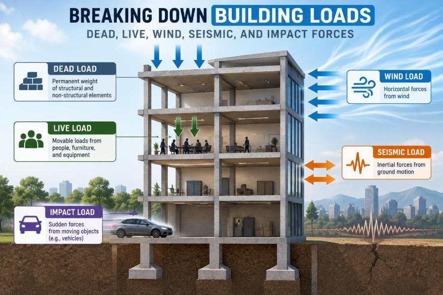
Dead load is the permanent gravity load from the building itself and fixed components. It includes structural framing, slabs, walls, roofs, permanent finishes, cladding, fixed ceilings, and permanently installed equipment.
Dead load is comparatively predictable because material unit weights and dimensions can be estimated from drawings. Yet it should not be treated casually. A thicker slab, heavier façade system, or added topping can increase column and foundation demands across every story below.
Dead load also influences long-term effects. Sustained compression can contribute to concrete creep, and sustained bending can affect deflection in timber or steel-concrete composite systems.
🧱 Estimating Permanent Weight Carefully
Dead-load calculations begin with volume and material unit weight. A concrete slab’s weight, for example, depends on its thickness, plan area, and the applicable concrete density. The calculation then grows to include screeds, waterproofing, pavers, ceilings, services allowances, and other fixed layers.
Common omissions are rarely dramatic on their own. They become significant when repeated over a large area or applied to many floors.
- Facade support brackets and heavy glazing systems
- Raised-floor assemblies and acoustic toppings
- Permanent partitions where the layout is known
- Roofing, insulation, ballast, and photovoltaic support systems
- Mechanical equipment that will not be routinely relocated
When a component’s final weight is uncertain, engineers should coordinate with architects and building-services teams rather than relying on an optimistic placeholder.
👥 Live Loads: Occupancy Changes the Demand
Live load, also called imposed load, comes from occupants and movable items: people, furniture, stored goods, movable partitions, and some maintenance activities. Unlike dead load, it can vary in position, magnitude, and duration.
A residential room, library stack area, office, assembly hall, and warehouse do not have the same loading pattern. The use of the space determines both the expected intensity and the likelihood that a large area will be loaded at once.
Building codes provide occupancy-based minimum design loads, but the engineer must still verify that the intended use matches the selected category. A room labelled “storage” without information about what is stored is not enough for reliable design.
🪑 Local Loading Matters as Much as Averages
An evenly distributed floor load is convenient for global beam and column design, but real rooms often contain concentrated items. A safe, storage cabinet, compact filing bank, aquarium, or equipment rack can impose high localized reactions on a slab.
Imagine placing a heavy cabinet near the middle of a lightly reinforced slab panel. Its total weight may appear modest compared with the room’s overall design load, yet the concentrated footprint can govern punching shear, local bending, or deflection.
Design checks therefore need to match the physical situation: distributed-load checks for overall framing and concentrated-load checks where legs, wheels, supports, or equipment bases introduce local actions.
📉 Live-Load Reduction Has Limits
For large tributary areas, it may be unlikely that every portion reaches its maximum live load simultaneously. Many design standards permit specified live-load reductions for selected members under defined conditions.
This is a probability-based design allowance, not permission to assume lightly loaded floors. Reductions may be limited or prohibited for occupancies where high loading is persistent, such as storage areas, and for elements where the consequences or load behavior require a more conservative approach.
Engineers must apply the governing code provisions and understand what the reduction represents. A column supporting many office floors is not evaluated in the same way as a short beam serving a small room.
🌧️ Roof Loads Beyond Self-Weight
Roofs carry more than their own framing and covering. Depending on climate, form, drainage, and access, they may experience rain accumulation, snow, ice, maintenance personnel, landscaping, equipment, and temporary construction loads.
Ponding illustrates why geometry matters. If water collects on a flexible roof, the added weight can deepen the deflection, which holds more water and adds further load. Proper slope, drainage layout, overflow provisions, and stiffness all help interrupt this feedback.
Roof equipment can also create vibration and localized reactions. Its curbs, rails, maintenance routes, and replacement path should be coordinated early rather than added as an afterthought.
💨 Wind Begins as Pressure
Wind acts as moving air that produces pressure differences on building surfaces. On the windward face, air generally pushes inward. Over roof edges, corners, and leeward faces, suction can pull cladding or roofing outward.
These pressures depend on wind speed, terrain exposure, building height, shape, openings, topography, and local aerodynamic effects. The result is not a uniform shove across every surface.
For the primary structure, wind creates lateral shear, overturning moment, and sometimes torsion. For the building envelope, it creates direct demands on panels, fasteners, anchors, glazing, and roof assemblies—often most severe near edges and corners.
🏙️ Height and Shape Change Wind Response
Wind speed and turbulence characteristics can vary with elevation, so taller buildings often see larger wind demands higher up. Their slenderness and flexibility can make occupant comfort as relevant as member strength.
Shape matters too. A broad low building, a stepped tower, and a narrow rectangular tower disturb airflow differently. Re-entrant corners, canopies, parapets, and neighboring structures can produce localized effects that simplified intuition misses.
For unusual, very tall, or aerodynamically sensitive structures, specialized analysis and, where appropriate, wind-tunnel investigation may inform the design. Such work refines a specific project; it does not replace sound load paths and robust envelope detailing.
🌀 Gusts, Vibration, and Serviceability
Wind is often gusty rather than steady. A flexible structure can respond dynamically, moving back and forth as the wind fluctuates. This motion may be structurally acceptable while still being noticeable to occupants.
Serviceability concerns performance under normal or frequent conditions: drift, acceleration, cladding movement, door operation, water-tightness, and perceived comfort. It differs from ultimate strength, which focuses on avoiding collapse or severe failure under factored design actions.
A lateral system should therefore be evaluated for more than peak force. Stiffness, damping, mass distribution, and façade compatibility all affect the building’s real-world behavior.
🌍 Seismic Loads Come From Inertia
Earthquake loading is fundamentally different from a horizontal force applied directly by wind. Ground shaking moves the foundation, while the building’s mass resists that change in motion because of inertia. The resulting inertial forces act throughout the structure.
In a simplified sense, greater mass can produce greater seismic demand. That is why unnecessarily heavy upper floors, roofs, and façades can be consequential in seismic design.
Earthquakes also reverse direction rapidly. A beam-column joint, brace connection, or wall boundary must be able to respond through cycles of loading, not just resist a single push in one direction.
📈 Period, Mass, and Stiffness
A building has natural modes of vibration, or characteristic ways in which it tends to sway and deform. Its natural period is related to mass and stiffness: generally, a heavier or more flexible building has a longer period than a lighter or stiffer one.
Seismic analysis uses this dynamic behavior because different ground motions affect buildings differently. A simple static lateral-force procedure can be appropriate for regular, lower-complexity structures within its permitted scope. Irregular, taller, or more sensitive buildings may require more detailed dynamic analysis.
The objective is not to predict one exact earthquake response. It is to design for code-defined hazard and performance assumptions using methods suitable for the structure.
🧩 Ductility Is a Seismic Survival Tool
Ductility is the ability to deform significantly without sudden loss of strength. In seismic-resistant design, carefully selected regions may yield in a controlled manner, dissipating energy while the structure maintains a stable load path.
This does not mean “letting the building fail.” It means detailing certain components so that inelastic behavior occurs where it can be anticipated and tolerated, while brittle failures are prevented.
Examples include confinement reinforcement in concrete boundary zones, properly detailed steel connections, and capacity-based design that protects columns, joints, and connections from demands associated with yielding elements.
🧱 Lateral Systems: Frames, Walls, and Braces
Buildings resist wind and seismic effects through one or more lateral-force-resisting systems. The choice depends on height, layout, material, architectural constraints, soil conditions, and the governing hazard.
| System | Primary mechanism | Common consideration |
|---|---|---|
| Moment frame | Rigid beam-column bending | Open layouts, but drift control can govern |
| Braced frame | Axial tension and compression in braces | Efficient stiffness, with diagonal-space constraints |
| Shear wall | In-plane wall shear and bending | High stiffness; openings and foundations need care |
| Dual system | Combined frame and wall/bracing action | Requires compatible stiffness and force sharing |
No system is automatically superior. A well-detailed system with a clear path generally performs better than a theoretically efficient system compromised by discontinuities or poor coordination.
🔄 Torsion: When a Building Twists
Torsion occurs when the line of action of lateral force does not align with the building’s effective resistance. For example, if most shear walls are concentrated near one side of a floor plan, the building may translate and rotate during wind or earthquake loading.
This rotation can amplify demands at perimeter elements. Irregular plans, uneven stiffness, setbacks, and asymmetric mass distribution are common sources of torsional sensitivity.
Symmetry is helpful but not always architecturally possible. The practical goal is to recognize eccentricity, model it appropriately, provide a capable diaphragm, and avoid placing all lateral resistance in one isolated portion of the plan.
🧱 Diaphragms Collect and Distribute Lateral Forces
Floors and roofs often act as diaphragms, collecting lateral inertia or wind forces and distributing them to walls, frames, or braces. A concrete slab can form a stiff diaphragm; metal deck, timber sheathing, or precast systems may behave differently depending on detailing.
Diaphragm action relies on connections, chords, collectors, and boundary elements. Openings for stairs, atriums, shafts, and services can interrupt force flow and require deliberate reinforcement or framing around them.
It is a frequent conceptual mistake to design strong shear walls while overlooking the floor system that must deliver force to those walls.
🚗 Impact Loads Are Short and Local
Impact loads arise when moving objects strike a structure or when a force is applied abruptly. Vehicles hitting parking-garage columns, forklifts contacting warehouse walls, vessels striking piers, and dropped objects during industrial operations are familiar examples.
Because deceleration can occur over a short distance and time, impact may create forces much larger than those suggested by an object’s static weight alone. The exact response depends on speed, mass, stiffness, energy absorption, geometry, and whether the object rebounds, crushes, or slides.
Impact is often best addressed through prevention and protection as well as member strength.
🛡️ Designing for Vehicle and Equipment Protection
Where vehicles operate close to structural elements, layout is the first defense. Clear routes, adequate turning space, curbs, wheel stops, barriers, and protected loading zones can reduce the chance that a column becomes the last obstacle.
Bollards or crash barriers may protect vulnerable supports, but they need their own properly designed anchorage and foundation. A lightweight barrier that detaches under contact can transfer little useful protection.
Equipment loads require similar attention. A vibrating machine may impose dynamic forces, while a crane runway or movable hoist creates changing wheel loads, lateral effects, and fatigue-sensitive details.
🧨 Construction Loads Are Not the Final Building Loads
A structure can be most vulnerable before it is complete. Fresh concrete, stacked materials, formwork, temporary bracing, partially installed precast units, and construction equipment can create load cases absent from the finished building.
Temporary conditions may lack the final diaphragm, composite action, lateral bracing, or connection capacity assumed by the completed design. Removal of shores and sequencing of pours can also redistribute forces.
Construction engineering is therefore a structural problem in its own right. Responsibilities for temporary works, erection stability, and loading limits should be clear among the relevant project parties.
🧮 Load Combinations Reflect Realistic Extremes
Buildings are not normally checked for every possible load at its maximum value simultaneously. Instead, design standards specify load combinations that represent credible combinations of permanent, variable, environmental, and accidental actions.
Different factors are applied because uncertainty and variability differ among load types. Dead load is relatively stable; occupancy, wind, and seismic actions have different statistical behavior and modeling uncertainty.
The precise combinations, factors, and permitted methods come from the adopted building code and referenced standards. Engineers must use the requirements applicable to the project location and material system rather than borrowing values from unrelated examples.
🏋️ Strength Design and Serviceability Checks
Strength design asks whether a component can resist factored demands with the required safety margin. Typical checks include flexure, shear, axial force, buckling, connection strength, and foundation bearing or uplift.
Serviceability asks whether the building performs acceptably in use. A floor can be strong enough yet vibrate unpleasantly. A beam can be safe yet deflect enough to crack brittle finishes. A tall wall can resist wind yet permit drift that damages partitions or façade seals.
Good design satisfies both sets of requirements. Treating serviceability as cosmetic can create expensive and disruptive problems after occupancy.
📐 Load Cases Need a Model That Matches Reality
Structural models simplify real buildings. Supports may be idealized as fixed or pinned; floors may be represented as rigid or flexible diaphragms; member connections may be assigned releases or stiffness. Every simplification has consequences.
A useful model captures the behavior that matters for the decision being made. For example, assuming a perfectly rigid diaphragm may be unsuitable for a long, irregular roof with flexible deck and large openings.
Software can rapidly analyze many load combinations, but it does not verify assumptions. Engineers still need independent checks of reactions, deflected shapes, force flow, units, restraint conditions, and whether the output makes physical sense.
🔍 Common Load-Assessment Mistakes
Many serious design problems begin with incomplete information rather than difficult mathematics. The following errors deserve routine attention:
- Using an occupancy load that does not match the owner’s intended use
- Ignoring permanent finishes, façade weight, or future roof equipment
- Treating a concentrated machine load as a uniform floor load
- Assuming a lateral wall is effective without a complete diaphragm connection
- Overlooking torsion caused by an asymmetric layout
- Checking the final building but not temporary construction stages
- Applying code load values without confirming the correct edition, location, and exposure assumptions
Each mistake interrupts the relationship between the physical building and the calculation model.
🛠️ Coordination Changes Structural Demand
Load decisions are shared across disciplines. An architect’s choice of stone cladding, a mechanical team’s rooftop plant, a tenant’s storage plan, or a contractor’s erection sequence can change structural demands substantially.
Early coordination questions are practical: Where will equipment sit? Can it be replaced? Which walls are permanent? Are future fit-outs expected? Will large penetrations cross the diaphragm? Where can delivery vehicles travel?
Documented assumptions are valuable because buildings evolve. If an assumed light-use room later becomes an archive or equipment room, the structural implications should be reviewed before the change occurs.
🏚️ Existing Buildings Need Verification, Not Guesswork
Assessing an existing building introduces uncertainty about materials, reinforcement, connection details, alterations, deterioration, and original design assumptions. Drawings can help, but they may not reflect later renovations or field conditions.
Site investigation, measured dimensions, selective probing, material testing where appropriate, and review by a qualified engineer can reduce uncertainty. The scope should match the decision: a proposed rooftop unit may require different information than a major change of occupancy.
A conservative assumption can be prudent, but indiscriminate conservatism may also lead to unnecessary work. The best approach is evidence-based evaluation within the limits of available information.
📋 A Practical Load-Review Workflow
A disciplined sequence helps keep load analysis traceable:
- Define the structure, support conditions, intended occupancy, and project location.
- List permanent, variable, environmental, construction, and accidental actions.
- Establish load paths for gravity and lateral forces.
- Identify concentrated loads, openings, discontinuities, and likely future changes.
- Select code-based load criteria and combinations applicable to the project.
- Analyze strength, stability, drift, deflection, vibration, and connection demands.
- Review results against simple hand checks and physical intuition.
- Coordinate assumptions and revise the design as architecture and services develop.
This workflow does not eliminate engineering judgment; it makes that judgment visible and easier to review.
🎯 The Core Principle: Every Load Needs a Reliable Route
Dead, live, wind, seismic, and impact loads differ in duration, direction, predictability, and physical mechanism. Dead load is persistent; live load moves with use; wind acts through pressure and suction; earthquakes create inertia; impact delivers energy abruptly.
Yet every category leads back to the same structural question: Can the building transfer this action through a continuous, adequately strong and adequately stiff path to the ground?
That question applies to a slab beneath a filing cabinet, a roof under ponded water, a façade connection at a wind-exposed corner, and a shear wall receiving seismic force from a floor diaphragm. Understanding the route is what turns isolated load values into safe structural decisions.
Reliable structures begin with realistic loads, continue through complete load paths, and are confirmed by careful checks of both strength and performance. 🏗️💨🌍