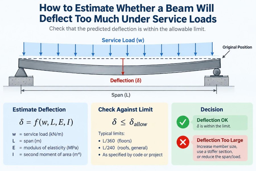

A floor can feel springy even when its beams are perfectly safe against collapse. A shelf can visibly sag long before its material reaches a breaking stress. A roof member may hold every intended load yet create ponding, cracked finishes, sticking doors, or an uncomfortable sense of movement.
That gap between “strong enough” and “stiff enough” is where serviceability design begins. Deflection is the change in position of a structural member under load, and it often governs the design of beams used in floors, roofs, platforms, lintels, and equipment supports.
For students, beam deflection can seem like a formula-selection exercise. For practicing engineers, it is a judgment exercise: identify the real support condition, load path, stiffness, duration of loading, and performance criterion before trusting a calculated number.
A sound preliminary estimate will not replace a complete design check. It can, however, reveal whether a beam concept is plausible, where detailed analysis is needed, and why a beam that passes strength calculations may still perform poorly.
🎯 Start with the Serviceability Question
Beam deflection is normally evaluated at service loads: the loads expected during ordinary use. This differs from strength design, which commonly uses factored load combinations to protect against yielding, rupture, buckling, or collapse.
The question is not simply “How many millimetres will it move?” It is “Will that movement interfere with the structure’s intended use, attached finishes, drainage, equipment, or occupants’ expectations?” A warehouse rack beam, a plaster ceiling support, and a pedestrian bridge can have very different acceptable responses.
📏 What Deflection Actually Means
Deflection is displacement caused by deformation. In a typical horizontal beam, engineers are usually concerned with vertical displacement, especially the maximum downward movement near midspan.
Deflection is not the same as rotation. A beam can have a modest midspan deflection but a significant end rotation, which may matter where it supports brittle cladding, a partition, or a sloped roof surface.
It is also not the same as vibration. Deflection describes a position under load; vibration describes motion over time. The two are related because a flexible beam may be more prone to perceptible vibration, but one check does not automatically satisfy the other.
🏠 Why Small Movements Can Create Large Problems
People usually notice deflection through its consequences rather than through measurements. Ceiling cracks, uneven flooring, ponded water, misaligned glazing, and doors that no longer latch are common warning signs of movement somewhere in the supporting system.
Some movement is expected and harmless. The concern begins when it exceeds the tolerance of connected materials or disrupts function. A concrete slab may tolerate gradual curvature differently from a brittle gypsum partition attached below it.
- Roof deflection can reduce drainage slope and encourage water accumulation.
- Floor deflection can damage finishes or make occupants feel movement.
- Facade support deflection can impose unintended stresses on glass, masonry, or panels.
- Machinery-support deflection can affect alignment and operation.
⚖️ Strength and Stiffness Are Different Checks
Strength asks whether internal forces and stresses remain within safe limits. Stiffness asks whether the member deforms acceptably. Increasing beam depth often helps both, but not at the same rate.
A high-strength steel beam is not automatically a stiff beam. Steel’s elastic modulus is essentially the same across common structural grades, so changing to a stronger grade may improve strength capacity while making little difference to elastic deflection.
This distinction is central to efficient design: when deflection governs, the most useful change is often geometric rather than a higher-strength material grade.
🧱 The Four Main Inputs to a Deflection Estimate
Most elastic beam-deflection calculations depend on four physical ingredients: loading, span, support condition, and flexural stiffness. If any of these is badly idealized, a precise-looking answer can still be misleading.
| Input | What it represents | Why it matters |
|---|---|---|
| Load, w or P | Distributed or concentrated service load | More load causes more curvature and displacement. |
| Span, L | Distance between effective supports | Deflection rises very rapidly as span increases. |
| Elastic modulus, E | Material resistance to elastic strain | Higher E generally means less deflection. |
| Second moment of area, I | Sectional resistance to bending curvature | Greater depth and efficient shape greatly increase stiffness. |
📦 Identify the Loads Before Doing Any Math
Service loading may include self-weight, permanent finishes, partitions, ceilings, stored materials, people, snow, rainwater, equipment, and construction loads. Not all loads act together at their full nominal values in every design situation, so the applicable design standard and project criteria matter.
For a first estimate, write each load source separately. This prevents a frequent mistake: calculating only imposed live load and forgetting the beam’s self-weight, slab weight, decking, ceiling, or accumulated roof build-up.
Line load is especially convenient for a beam. An area load on a floor or roof becomes a line load by multiplying by the beam’s tributary width, meaning the share of surface area that delivers load to that beam.
🗺️ Convert Area Load into Beam Line Load
Suppose a floor carries a service area load of 5 kN/m², including its relevant permanent and imposed components for the check. If an interior beam supports a tributary width of 3 m, the floor contributes:
line load = area load × tributary width
w = 5 kN/m² × 3 m = 15 kN/m
The beam’s own weight must then be added. This simple conversion works when the floor load is distributed regularly and framing action is clear. Irregular slab spans, concentrated reactions from secondary beams, openings, and discontinuous load paths may require a more careful model.
📐 Span Has an Outsized Effect
For common simply supported beam cases, deflection is proportional to the fourth power of span, L⁴. Doubling the span does not double deflection; with other variables unchanged, it increases it sixteenfold.
This is why modest layout changes can transform a design. Moving a support, introducing a secondary beam, or reducing bay size may be more effective than selecting a much heavier section.
Use the effective span appropriate to the actual support arrangement. The clear distance between faces of supports is not always the same as the theoretical span used in beam formulas or code provisions.
🪑 Support Conditions Control the Shape
A beam’s supports determine how it can rotate and translate. The familiar “simply supported” model allows end rotation and prevents vertical movement. A cantilever is fixed at one end and free at the other. A fixed-ended beam restrains rotation at both ends.
Rotational restraint can reduce deflection substantially, but it should never be assumed casually. A connection that is strong enough to transfer shear may still be flexible in rotation. Real restraint depends on connection details, supporting members, construction sequence, and the stiffness of the entire frame.
🧮 Useful First-Pass Beam Formulas
For a prismatic, linearly elastic beam of constant EI, common textbook cases provide fast screening estimates. Keep units consistent: if E is in N/mm² and I is in mm⁴, use load in N/mm and span in mm to obtain deflection in mm.
| Beam case | Maximum deflection | Location |
|---|---|---|
| Simply supported, uniform load w | 5wL⁴ / 384EI | Midspan |
| Simply supported, central point load P | PL³ / 48EI | Midspan |
| Cantilever, end point load P | PL³ / 3EI | Free end |
| Cantilever, uniform load w | wL⁴ / 8EI | Free end |
These formulas are not universal. They do not directly cover varying sections, partial loading, multiple spans, semi-rigid connections, nonlinear material behavior, large deformation, or complex composite action.
🔢 Keep Units Under Strict Control
Unit errors can make a reasonable beam appear impossibly stiff or disastrously flexible. The fourth power on span magnifies even small conversion mistakes.
A dependable mm-based workflow is to use load in N/mm, span in mm, elastic modulus in N/mm², and second moment of area in mm⁴. Remember that 1 kN/m equals 1 N/mm, which is convenient, while 1 kN/m² does not become a line load until tributary width is applied.
Write units beside every intermediate value. This is faster than trying to diagnose a result after the fact.
🧠 Understand Flexural Stiffness, EI
The product EI is flexural stiffness. Elastic modulus E belongs to the material; second moment of area I belongs to the cross-sectional shape and bending axis.
A beam bends because bending moment produces curvature. In simplified elastic theory, curvature increases as moment increases and decreases as EI increases. This is why a beam’s depth and orientation matter so much.
For materials such as timber, E can vary by grade, species, moisture condition, duration of load, and direction relative to grain. For concrete, effective stiffness changes as cracking and time-dependent behavior develop. Treating every material as a perfectly constant elastic solid can be a poor approximation.
📊 Why Depth Is Usually the Fastest Lever
For a rectangular section bending about its strong axis, I = bh³/12, where b is width and h is depth. Depth is cubed, so increasing it is exceptionally powerful.
If depth doubles while width stays constant, the second moment of area becomes eight times larger. For an elastic beam with the same loading and span, the bending deflection becomes roughly one-eighth.
This explains why turning a rectangular member “on edge” makes it much stiffer than laying it flat. It also explains the efficiency of I-shapes: material is placed far from the neutral axis, where it contributes strongly to bending stiffness.
🔄 Check the Correct Bending Axis
Every section has principal axes, and the relevant I depends on the direction of bending. A steel I-beam loaded vertically is normally intended to bend about its strong axis. Using its weak-axis property by mistake can change the estimated deflection dramatically.
The same issue appears in rectangular timber, channels, angles, and hollow sections. Confirm the member orientation in the actual structure, not just in a section-property table.
🧾 A Worked Screening Example
Consider a hypothetical simply supported steel beam spanning 6,000 mm under a uniform service load of 10 N/mm. Suppose its strong-axis second moment of area is 85 × 10⁶ mm⁴ and take E as 200,000 N/mm² for an initial elastic estimate.
δmax = 5wL⁴ / 384EI
δmax = 5(10)(6000⁴) / [384(200000)(85 × 10⁶)]
δmax ≈ 10 mm
This result is only a screening value. The next step is to compare it with the project’s applicable deflection criterion and verify that the assumed loading, span, support condition, and section property are correct.
Notice the discipline of the calculation: it does not announce that 10 mm is acceptable or unacceptable without context. A numerical deflection has meaning only against a relevant limit and the behavior of what the beam supports.
📏 Use Deflection Limits as Performance Criteria
Deflection criteria are often expressed as a span ratio, such as L/xxx. The denominator and the load combination depend on the governing code, structural system, supported finishes, occupancy, and client requirements.
For example, a limit based on total deflection may differ from one based on live-load deflection or deflection occurring after sensitive finishes are installed. A roof with drainage requirements may need a check tailored to maintaining slope, not merely a generic span ratio.
Do not treat one familiar L/number as a universal rule. Use the requirements applicable to the project and ask what component is actually vulnerable to movement.
🧩 Total, Live, and Incremental Deflection
Total deflection is the movement under the relevant accumulated service load. Live-load deflection is the movement associated with variable occupancy or use. Incremental deflection can mean the movement that occurs after a finish, partition, facade element, or other sensitive component is installed.
This distinction matters because a partition may tolerate the beam’s earlier dead-load sag if it was built after that sag occurred, but it may crack when later live load causes additional movement. Construction sequence is therefore part of serviceability reasoning.
⏳ Long-Term Effects Can Govern
Some deflection develops slowly. Timber can exhibit creep under sustained load, especially where moisture conditions and load duration are unfavorable. Concrete may experience creep and shrinkage, while cracking reduces the effective stiffness used for serviceability analysis.
Long-term deflection is not reliably captured by inserting an instantaneous elastic modulus into a simple formula and stopping there. Material-specific methods in the applicable design standard usually address sustained loading, cracking, creep, and environmental effects.
Steel beams can also create long-term serviceability concerns through connected systems, even though steel itself does not creep at ordinary building temperatures in the same way as concrete or timber. Settlement, connection slip, and changing loads can still alter observed levels.
🧱 Cracking Changes Reinforced Concrete Stiffness
Before significant cracking, a reinforced concrete beam may behave closer to its gross uncracked section. After cracking in tension zones, its stiffness reduces, though the tension reinforcement and concrete between cracks still contribute to behavior.
Using the gross concrete section throughout can underestimate deflection. Using an overly conservative fully cracked stiffness everywhere can be unnecessarily pessimistic. Design procedures address this through effective stiffness or curvature methods that represent the member’s expected service condition.
Concrete serviceability checks also require attention to reinforcement amount, member depth, sustained loads, shrinkage restraint, and support conditions. A single hand formula is useful for intuition, not a substitute for the relevant concrete design method.
🌲 Timber Requires Material-Specific Judgment
Timber is anisotropic: its properties depend on direction. It also varies naturally, which is why graded products and manufacturer data are essential. Moisture changes can affect stiffness, connection behavior, and long-term movement.
Engineered wood products may offer more predictable geometry and properties than sawn lumber, but their deflection behavior still depends on the product type, orientation, web or flange details where applicable, bearing, and connection layout. Do not substitute a generic timber modulus without checking the specified product data and design provisions.
🔗 Composite Action Is Valuable but Conditional
A steel beam and concrete slab, or a timber beam and deck, may act compositely if connectors and detailing transfer longitudinal shear between components. When genuine composite action develops, stiffness can be much greater than that of the beam alone.
But composite behavior cannot be assumed because two materials touch. Fastener spacing, shear-connector capacity, slip, slab reinforcement, construction stage, and the design standard’s effective-width rules all affect the result.
For preliminary work, state clearly whether the estimate assumes bare-beam stiffness, partial composite action, or full composite action. Hidden assumptions are more dangerous than conservative assumptions that are openly identified.
🏗️ Continuous Beams Behave Differently
A continuous beam across multiple supports usually deflects less at midspan than separate simply supported spans because continuity develops negative bending moments over supports. It may also create upward deflection, or hogging, near supports.
The benefit depends on the continuity being real throughout the relevant loading and construction stages. A nominally continuous member with flexible splices, staged loading, or cracking near supports may not achieve the idealized response.
Continuity also shifts moments. Reducing one serviceability problem can increase demands elsewhere, so strength, detailing, and crack control must be checked together.
🪛 Connections and Bearing Can Add Movement
Simple beam formulas often assume supports are immovable and connections have no slip. In practice, bolts may settle into holes, timber bearing may compress, steel seats may rotate, and foundation or column movement may contribute to the observed deflection.
For short, deep, or heavily loaded members, local bearing deformation can be a meaningful portion of total movement. For long-span systems, connection flexibility can affect vibration and overall serviceability even when beam bending dominates static deflection.
🌊 Watch for Ponding and Load Redistribution
Roof deflection deserves special care where water can collect. Downward movement may create a low point, which retains more water, adds load, and causes further movement. This interaction is known as ponding and can be more serious than a one-way calculation with a fixed rain load suggests.
Drain location, roof slope, deck stiffness, overflow provisions, and framing geometry all matter. A roof beam should not be judged by a generic floor criterion if drainage performance is the controlling concern.
🚶 Deflection Is Not a Complete Floor-Comfort Check
A floor may satisfy a static deflection limit and still feel lively under footfall. Human perception responds to frequency, damping, mass, walking patterns, and the spatial behavior of the floor system.
Conversely, a floor with visible long-term sag may feel relatively firm during walking. Static deflection and vibration should be treated as related but separate serviceability checks, particularly for long-span lightweight floors, offices, residences, gyms, and assembly spaces.
🧮 When Hand Calculations Are Enough
Hand calculations are excellent for preliminary sizing, checking software outputs, understanding sensitivity, and identifying unreasonable assumptions. They are especially effective for regular beams with simple support conditions and clear loading.
A spreadsheet can extend this approach for several load cases, but it must preserve transparent units and formulas. A spreadsheet that hides assumptions is not automatically more reliable than a handwritten calculation.
Use a more complete analysis when geometry, loading, material behavior, or support restraint makes the standard cases unrepresentative.
💻 Know When a Structural Model Is Needed
Frame analysis or finite-element modeling can represent continuous spans, varying loads, complex geometry, diaphragm behavior, semi-rigid connections, and interaction among members. It is valuable when the load path cannot honestly be reduced to a single textbook beam.
However, software does not remove engineering judgment. Model boundary conditions, releases, mesh density, stiffness modifiers, load application, and construction stages can dominate the answer. A model should be checked against simple expected behavior: Does the deflected shape make physical sense? Are reactions plausible? Does a rough hand estimate agree in order of magnitude?
⚠️ Common Errors That Underestimate Deflection
- Using a factored-strength calculation but omitting the relevant serviceability load case.
- Forgetting self-weight, finishes, ceilings, partitions, or equipment loads.
- Assuming fixed ends when the real connections are simple shear connections.
- Using gross concrete stiffness after cracking without justification.
- Ignoring creep, shrinkage, moisture effects, or sustained loading.
- Using the wrong axis or incorrect section property.
- Confusing metres with millimetres, especially in an L⁴ term.
- Comparing total deflection with a limit intended for live-load or incremental deflection.
Most of these errors are not arithmetic mistakes. They are modeling mistakes, which is why documenting assumptions is as important as showing the equation.
🛠️ Practical Ways to Reduce Deflection
The best solution depends on the constraint. If depth is available, increasing beam depth is often the most efficient move. If floor-to-floor height is limited, reducing span with an intermediate support or changing the framing direction may be preferable.
- Increase section depth or use a more efficient section shape.
- Reduce the effective span with supports, secondary framing, or a revised layout.
- Add genuine continuity or composite action where detailing can support it.
- Reduce permanent load through lighter finishes or roof build-up.
- Use camber where appropriate to offset predicted dead-load deflection.
- Separate brittle finishes from movement-sensitive framing where feasible.
Camber deserves restraint: it offsets an anticipated deflection but does not increase stiffness. Excessive or poorly estimated camber can create unwanted upward curvature under light loading.
🧭 A Repeatable Preliminary Check
- Define the beam, its effective span, section, material, and support assumptions.
- List service loads separately and convert area loads to line loads using tributary width.
- Select a load pattern and beam formula consistent with the assumed structural behavior.
- Use consistent units to calculate an initial elastic deflection.
- Compare the result with the applicable criterion for total, live, or incremental movement.
- Consider material-specific long-term effects, cracking, connection movement, and construction sequence.
- Revise the concept or complete a more detailed analysis where uncertainty is material.
This sequence keeps the calculation connected to physical reality instead of turning it into a detached formula exercise.
✅ The Core Principle: Model the Real System
A beam does not deflect according to its section size alone. Its response comes from the interaction of load, span, stiffness, restraint, time, and the components attached to it. The formula is only as credible as those inputs.
For quick estimates, start with a conservative, clearly stated model and use it to compare alternatives. A result that is close to the allowable movement, depends on uncertain restraint, or involves long-term material effects deserves a refined check by a qualified structural engineer.
Serviceability is ultimately about performance in use. A beam that remains stable but creates cracked finishes, ponding water, or an uncomfortable floor has not fully met the needs of the structure.
Estimate deflection by understanding the real load path and stiffness first, then use calculations to test whether that behavior is acceptable in service. 🏗️📐✅