
A shelf loaded with books, a lintel over a window, and a floor joist beneath a room all do the same quiet job: they span a distance while carrying load. They may look rigid, but each one bends slightly as the load is transferred to its supports.
That bending creates internal stress. If the stress is too high, a timber member may crack, a steel beam may yield, or a concrete member may develop wider cracks than intended. The beam does not need to collapse for bending stress to matter; excessive deflection and cracking can make a structure unusable long before that point.
For a simple, slender beam under ordinary elastic behavior, bending stress can be calculated with one compact equation. Using it correctly, however, depends on understanding where the bending moment comes from, where the critical fibers are, and which section property actually describes resistance to bending.
This guide develops the calculation step by step, then works through a complete hypothetical example and highlights the checks that a real design still requires.
🧱 What Bending Stress Means
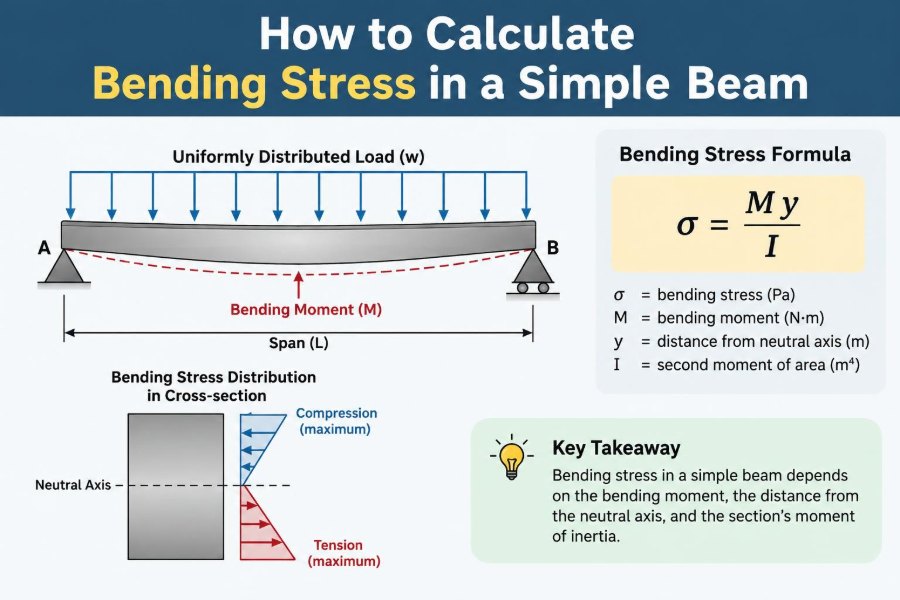
Bending stress is normal stress caused by a bending moment. Unlike shear stress, which acts parallel to a cross-section, bending stress acts along the beam’s length: one region is in compression and the opposite region is in tension.
Imagine bending a plastic ruler. Its upper surface shortens while its lower surface stretches. A beam behaves similarly, although the compressed and tensioned faces depend on the direction of the applied moment.
📐 The Basic Flexure Formula
The familiar elastic bending equation is:
σ = Mc / IHere, σ is bending stress at a chosen point, M is the internal bending moment at the section, c is the distance from the neutral axis to that point, and I is the second moment of area about the neutral axis.
At the outermost fiber, c is at its largest, so the bending stress is also largest. For most preliminary checks, that extreme-fiber stress is the value of interest.
🧭 Start with the Structural Idealization
Before calculating anything, state the beam model clearly. A simply supported beam has supports that permit rotation at both ends, commonly idealized as a pin at one end and a roller at the other.
This model is not appropriate for every real member. A cantilever, fixed-ended beam, continuous beam, or beam with semi-rigid connections develops a different moment distribution even under the same load.
- Identify the clear span between support reaction points.
- Identify support conditions and any overhangs.
- List all loads and where they act.
- Confirm that the member is reasonably slender and acting primarily in bending.
⚖️ Separate Loads from Reactions
External loads are applied to the beam; support reactions are forces supplied by the supports to keep the system in equilibrium. You need both before drawing shear and moment diagrams.
For a simply supported beam with only vertical loading, use equilibrium:
ΣFy = 0
ΣM = 0
Taking moments about one support often gives the reaction at the other support directly. Then the vertical-force equation provides the remaining reaction.
🪨 Recognize Common Load Types
A point load is concentrated at one location, such as a machine load carried by a beam. A uniformly distributed load, often written as w, is spread evenly along a length, such as a simplified representation of floor loading.
Real loads can also vary linearly, occur over only part of a span, or combine several forms. Replace no load with a convenient simplification unless that simplification is conservative and suitable for the purpose of the calculation.
📊 Why the Bending-Moment Diagram Matters
The bending-moment diagram shows the internal moment at every position along the beam. Since bending stress is proportional to M, the location of the largest absolute moment is usually the first place to check for maximum bending stress.
A moment diagram is not merely a drawing convention. It is the map that connects loading to stress. A correct section property cannot rescue a calculation based on the wrong peak moment.
🔁 Connect Load, Shear, and Moment
There is a useful sequence: distributed load changes shear, and shear changes bending moment. In calculus form, the slope of the moment diagram equals the shear force, subject to the selected sign convention.
Consequently, a maximum or minimum bending moment commonly occurs where the shear force crosses zero. This provides a quick way to locate a critical section under distributed loading.
📍 Maximum Moment for a Central Point Load
For a simply supported beam of span L carrying one point load P at midspan, the reactions are equal:
RA = RB = P / 2The greatest moment occurs at midspan:
Mmax = PL / 4This compact result applies only when the load is exactly at the center and the supports match the simple-support idealization. Moving the load off center changes both reactions and the maximum moment.
🌧️ Maximum Moment for a Uniform Load
For a full-span uniformly distributed load w on a simply supported beam, each reaction equals wL/2. The moment is greatest at midspan:
Mmax = wL² / 8The squared span term is significant. Doubling the span while keeping load intensity unchanged increases this maximum moment by a factor of four, which explains why longer spans quickly demand deeper or stronger members.
📏 Use Compatible Units from Beginning to End
Unit inconsistency is among the most common sources of implausible bending-stress results. Use one coherent system and write units beside every quantity while working.
| Quantity | Consistent SI example | Resulting stress unit |
|---|---|---|
| Moment M | N·mm | N/mm² |
| Distance c | mm | N/mm² |
| Second moment I | mm⁴ | N/mm² = MPa |
If moment is calculated in kN·m, convert it before combining it with c in millimeters and I in mm⁴. Specifically, 1 kN·m equals 1,000,000 N·mm.
🎯 Find the Neutral Axis
The neutral axis is the line in the cross-section where longitudinal bending stress is zero. For a homogeneous, symmetric section in elastic bending, it passes through the centroid.
For a rectangular section, the centroid lies halfway through the depth. For an unsymmetrical, built-up, or composite section, finding the neutral axis requires more care because the centroid may not be at mid-depth.
🧮 Understand the Second Moment of Area
The second moment of area, I, describes how cross-sectional area is distributed relative to an axis. Area placed farther from the neutral axis contributes much more strongly than area close to it.
It is a geometric property, not a material property. Two beams with identical dimensions have the same I even if one is steel and the other is timber; their allowable stresses and stiffness behavior will still differ because their materials differ.
📦 Calculate I for a Rectangular Beam
For a solid rectangle bent about its strong centroidal axis:
I = bh³ / 12In this expression, b is the width and h is the depth measured in the bending direction. The cubed depth is why rotating a rectangular member 90 degrees can drastically reduce its bending capacity and stiffness.
For this same rectangle, the extreme-fiber distance is:
c = h / 2🔧 Use Section Modulus for Faster Checks
Because c and I appear together repeatedly, engineers use the elastic section modulus:
S = I / cThe flexure formula becomes:
σmax = M / SFor a rectangular section, S = bh²/6. This shows a useful design relationship: at fixed width, doubling depth increases elastic bending resistance by a factor of four.
🏗️ Read Steel Section Properties Carefully
Rolled steel shapes are commonly supplied with tabulated values of I and S about their principal axes. An I-shaped section usually has a much larger major-axis section modulus than minor-axis section modulus.
Check the orientation shown on the drawing. A beam selected for strong-axis bending can be inadequate if installed or braced so that it bends about its weak axis. Tabulated values also do not automatically account for local buckling, lateral instability, holes, or connection effects.
🪵 Account for Material Behavior
The equation σ = Mc/I gives stress from geometry and load effect. Whether that stress is acceptable depends on the material and the governing design method.
Steel may be checked against yield-related resistance with required safety factors. Timber design values can depend on species, grade, load duration, moisture condition, size, and stability. Reinforced concrete is usually analyzed using cracking, reinforcement, and nonlinear material behavior rather than treating the entire gross section as a simple homogeneous elastic rectangle.
🧪 Assumptions Behind Elastic Beam Theory
The basic flexure formula rests on assumptions that are often reasonable but not universal:
- Plane cross-sections remain plane after bending.
- Strains and stresses are within an elastic or suitably linear range.
- Deflections are small enough that geometry changes do not dominate behavior.
- The beam is slender enough that bending, rather than deep-beam action, is the main response.
- The section is prismatic, or section properties are evaluated appropriately where they change.
When these assumptions are poor, a more advanced analysis may be necessary. The formula remains a foundation, not a substitute for judgment.
🧾 A Complete Hypothetical Example
Consider a simply supported solid rectangular beam with a span of 4,000 mm. It carries a central point load of 10 kN. Assume the section is 100 mm wide by 200 mm deep, with the 200 mm dimension vertical. This is a calculation example, not a design recommendation for any particular material.
First calculate the maximum moment:
Mmax = PL / 4
= (10 kN)(4 m) / 4
= 10 kN·m
= 10,000,000 N·mm
Next calculate the section properties:
I = bh³ / 12
= 100(200³) / 12
= 66,666,667 mm⁴ (approximately)

c = h / 2 = 100 mm
Now apply the flexure formula:
σmax = Mc / I
= (10,000,000)(100) / 66,666,667
= 15 N/mm², approximately
The maximum elastic bending stress is therefore approximately 15 MPa. The next question is not “is 15 a small number?” but whether it satisfies the relevant material resistance, load combination, serviceability, and stability requirements.
🔍 Check Both Tension and Compression Faces
Under sagging moment in a typical simply supported beam with downward load, the top fibers are in compression and the bottom fibers are in tension. At the same distance from a central neutral axis, their elastic stress magnitudes are equal and their signs are opposite.
This distinction matters because materials can behave differently in tension and compression. Concrete, for example, has limited tensile resistance compared with compression and is normally reinforced where tension is expected.
↕️ Know the Difference Between Shear and Bending
Maximum shear force and maximum bending moment generally occur at different locations. For a simply supported beam with a central point load, shear is greatest near the supports while bending moment is greatest at midspan.
A beam may therefore pass a bending-stress check but fail a shear check near a support, particularly if it is short and deep or carries high concentrated reactions. Do not use a bending calculation as a complete beam design.
📉 Deflection Is a Separate Serviceability Check
Bending stress tells you about material demand; deflection tells you how much the beam moves. A member can have acceptable stress yet deflect enough to damage finishes, pond water, cause vibration concerns, or make a floor feel uncomfortable.
Deflection depends on load, span, support conditions, the modulus of elasticity E, and I. Unlike bending stress, it depends directly on material stiffness through E. Long-span members often become deflection-controlled before bending strength becomes critical.
🪢 Prevent Lateral-Torsional Buckling
A slender steel beam in compression at its top flange can move sideways and twist before its calculated flexural stress reaches the material’s nominal yield level. This is known as lateral-torsional buckling.
Floor slabs, decking, purlins, cross-frames, or other restraints can provide bracing, but their effectiveness must be established rather than assumed. The simple formula calculates stress in the section; it does not prove that the beam will remain stable in that position.
🧩 Treat Openings, Notches, and Connections with Care
Holes, web openings, notches, coping, and connection details alter the load path and can create local stress concentrations. A small opening may be acceptable in one location and problematic in another depending on shear, moment, buckling, and fabrication details.
Timber notches near supports can significantly reduce shear capacity. Steel web openings require dedicated checks, and bolt holes may affect net-section behavior. Do not simply apply the gross-section value of I where the section has been materially reduced.
🔄 Handle Multiple Loads Systematically
When a beam carries several point loads, distributed loads, and self-weight, calculate reactions from the complete loading arrangement first. Then determine shear and moment piece by piece, or use a validated analysis method.
Superposition can be useful for linear elastic structures: calculate the moment contribution from each load case and add them. It is valid only where the structural response and boundary conditions are compatible with linear behavior.
🧠 Keep Sign Conventions Consistent
Different textbooks and software packages may define positive moment differently. The numerical maximum stress magnitude is unaffected by the choice, but the sign indicates which face is in tension or compression.
Choose a convention at the beginning. Mark positive and negative shear and moment clearly on sketches, especially when beams have overhangs, upward loads, or continuous spans where the moment reverses.
🛠️ A Reliable Hand-Calculation Workflow
A disciplined sequence makes simple beam calculations easier to review and harder to misinterpret:
- Sketch the beam, supports, dimensions, and all loads.
- Convert load units and dimensions into one consistent system.
- Calculate support reactions using equilibrium.
- Draw or calculate the shear-force diagram.
- Locate and calculate the maximum absolute bending moment.
- Identify the bending axis, neutral axis, I, and c.
- Calculate σ = Mc/I, including the stress unit.
- Check material resistance, shear, deflection, stability, and detailing as applicable.
A hand sketch is valuable even when software performs the final analysis. It gives you a physical expectation against which to compare output.
💻 Use Software as a Check, Not a Black Box
Spreadsheets and structural analysis programs can efficiently evaluate complex loading and continuous systems. Their results are only as reliable as the model: wrong support releases, load directions, member orientation, or units can produce polished but incorrect diagrams.
For a simple beam, independently estimate the reaction and peak moment using standard formulas. If a program disagrees, investigate the model rather than selecting the more convenient answer.
🚫 Avoid Frequent Calculation Mistakes
Several errors appear repeatedly in bending-stress work:
- Using total load where load intensity is required, or the reverse.
- Mixing meters with millimeters in I and c.
- Using the weak-axis property instead of the intended bending-axis property.
- Using the full depth as c instead of the distance from the neutral axis.
- Applying simply supported formulas to fixed or continuous beams.
- Comparing calculated stress directly to a material strength without the required design provisions.
Most of these are prevented by a labelled sketch, explicit units, and a final reasonableness check.
🧱 See Why Beam Depth Is So Effective
For a rectangular beam, bending stress under a given moment is:
σmax = 6M / bh²Depth appears squared in the denominator. Increasing depth is therefore usually much more efficient for reducing bending stress than increasing width by the same percentage. The same geometric feature also increases I substantially, which helps control deflection.
This does not mean deeper is always better. Architectural limits, lateral stability, connection geometry, fire protection, and available member sizes can control the practical choice.
🧱 Understand Composite and Built-Up Sections
When two materials act together, such as a steel beam with a composite concrete slab, the neutral axis and effective stiffness depend on the connection and relative material stiffness. Slip between components can reduce composite action.
Built-up sections also need their own analysis. Components must be connected strongly enough to transfer the longitudinal shear that develops between them; simply placing pieces together does not guarantee that their combined I can be used.
🧭 Know When the Simple Formula Is Not Enough
Seek a more complete design analysis when the beam is deep relative to its span, has large openings, experiences significant axial force, undergoes large deflections, has variable geometry, or is made from materials with nonlinear response.
Seismic, fatigue, fire, impact, dynamic, and temporary construction conditions may introduce additional demands. Applicable codes and a qualified structural engineer are especially necessary where public safety, occupied structures, or regulated work is involved.
✅ The Core Principle to Remember
Calculating bending stress in a simple beam follows a clear chain: loads create reactions, reactions create shear and bending moment, and bending moment creates stress according to the section geometry.
The central relationship is σ = Mc/I, or σ = M/S at the extreme fiber. But it is only meaningful when M comes from the correct structural model, I and c refer to the correct bending axis, and the result is evaluated alongside shear, deflection, stability, and material-specific design requirements.
A reliable beam calculation is not just a formula substitution; it is a connected check of load path, moment, geometry, material behavior, and structural stability. With that habit, bending-stress calculations become both faster and more trustworthy. 🏗️📐