
A beam can look deceptively simple: a timber member over a doorway, a steel section supporting a floor opening, or a reinforced-concrete lintel above a window. Yet before that member is selected, someone must answer a basic question: what is it actually carrying?
That question is more than a matter of adding a few weights. Loads move through a building in a path—from people, furniture, roofs, floors, and walls, into beams, columns, foundations, and finally the ground. A missed tributary area or an incorrect support assumption can distort the entire calculation.
For students, a basic beam calculation is one of the clearest ways to connect structural theory with a real building. For working professionals, it is also a useful framework for checking drawings, reviewing early schemes, and communicating assumptions before detailed design begins.
The worked example below is deliberately simplified. It explains how to set up a reliable calculation, not how to certify a beam. Final design must follow the governing building code, applicable material standard, project load criteria, and review requirements.
🧭 Start With the Question the Beam Must Answer
A load calculation should begin with a defined purpose. Are you estimating a preliminary beam size, checking the load delivered to an existing support, or preparing input for a structural analysis model? Each task may require a different level of detail.
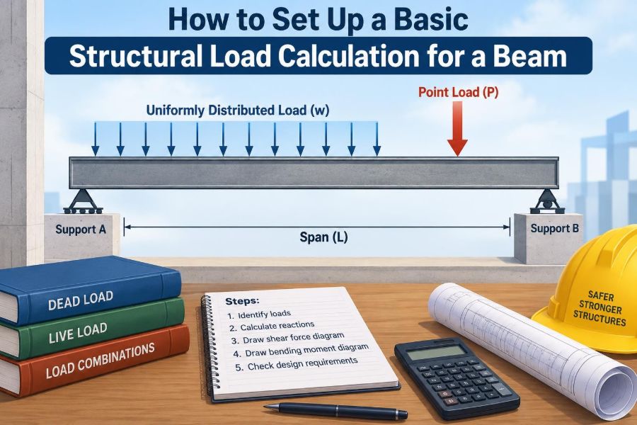
For a basic gravity-load check, the usual objective is to determine the beam’s line load, expressed as force per unit length, such as kN/m or lb/ft. Once that is known, reactions, shear forces, and bending moments can be calculated for a chosen support condition.
📐 Define the Beam Geometry First
Sketch the beam before inserting numbers. Show its span, support locations, adjacent framing direction, wall locations, and any concentrated loads. A clear freehand sketch often exposes missing information faster than a spreadsheet.
Record the clear span, support width, and the span used in analysis. Codes and design standards may define effective span differently for different materials and support arrangements, so do not assume the clear face-to-face distance is always the design span.
🧱 Identify the Structural System
A beam does not carry load in isolation. Determine whether it supports one-way joists, a slab, a masonry wall, roof purlins, another beam, or a mixture of these elements.
Most introductory beam calculations assume a one-way system: parallel joists span toward the beam from one or both sides. If a slab spans in two directions, or if framing is irregular, load distribution can be more complex and the tributary-area shortcut may not be sufficient.
🔄 Trace the Load Path
A load path is the route by which gravity load travels safely to the ground. For a typical floor, the path may be floor finish to slab or decking, then joists, then a beam, then columns or bearing walls, then foundations.
Trace this path in both directions. A beam may support joists directly, but it may also carry its own self-weight, a wall above, services hung below, or reactions from a secondary beam. Every item entering the beam should have a visible source on the sketch.
⚖️ Separate Dead, Live, and Environmental Loads
Dead load is permanent load: structural members, floor finishes, ceilings, fixed partitions where applicable, and permanently attached equipment. Live load is variable occupancy load, such as people, movable furniture, or stored materials.
Roofs may also receive snow, rain ponding, maintenance, or wind-related effects depending on the design situation. Seismic and wind actions are usually treated through lateral-system analysis rather than a basic vertical beam example, but they may affect connections and member design.
🗂️ Build a Load Schedule Before Combining Anything
A short load schedule keeps units, assumptions, and sources visible. Area loads are commonly written in kN/m² or psf; line loads in kN/m or plf; and point loads in kN or kips.
| Load item | Typical form | How it reaches the beam |
|---|---|---|
| Floor finish and slab | Area load | Through tributary width |
| Occupancy load | Area load | Through tributary width |
| Wall above | Line load | Directly along beam |
| Beam self-weight | Line load | Directly along beam |
| Framing reaction | Point load | At framing connection |
Use project-specific values from the applicable code, architectural information, and material data. The numerical values in a teaching example are never a substitute for those inputs.
📏 Understand Tributary Width
The tributary width is the width of floor or roof area that contributes load to a beam. For evenly spaced joists, it is generally measured halfway to the next parallel support on each side.
Imagine placing vertical cut lines at the midpoints between supports. The strip of floor bounded by those lines “belongs” to the beam for gravity-load calculation. Multiply that width by an area load to convert it to a line load.
↔️ Calculate One-Sided and Two-Sided Tributary Areas
If joists frame into only one side of a beam and span 3 m to another support, the beam’s tributary width is commonly 1.5 m: half the joist span. If joists frame into the beam from both sides with equal 3 m spans, the tributary width is 3 m.
This midpoint rule works for regular, uniformly loaded one-way framing. It must be reconsidered near cantilevers, offsets, openings, transfer conditions, or changes in framing direction.
🔢 Convert Area Load Into Line Load
The basic conversion is simple:
line load, w = area load, q × tributary width, bFor example, a combined unfactored floor area load of 6.0 kN/m² acting over a 3.0 m tributary width produces:
w = 6.0 kN/m² × 3.0 m = 18.0 kN/mThe units confirm the operation: square metres cancel, leaving force per metre. Unit checking is one of the fastest ways to catch an incorrect calculation.
🏋️ Add the Beam’s Self-Weight
Self-weight is often modest compared with a heavily loaded floor, but it should not disappear from a final calculation. For a steel beam, obtain mass per metre from the selected section table and convert it to weight. For concrete, use the member dimensions and the material unit weight.
At preliminary stage, an estimated self-weight may be acceptable if it is later updated after section selection. For a deep transfer beam or a long-span concrete beam, self-weight can be a significant part of total dead load.
🧱 Treat Walls as Direct Line Loads
A wall sitting continuously over a beam is usually modeled as a line load. Its weight depends on wall type, height, thickness, finishes, openings, and any supported floor or roof framing.
Do not convert a wall to an area load merely because it appears on a floor plan. Estimate or calculate its weight per metre, then add it directly to the beam’s line-load schedule. Partial-height walls and large openings may create a nonuniform load instead.
📍 Recognize Point Loads and Reactions
A secondary beam framing into a primary beam produces a point load equal to the secondary beam’s end reaction. A post, concentrated equipment support, or discontinuous wall segment can do the same.
Point loads matter because they can create local peaks in shear and bending moment. They also demand attention to web crippling, bearing, stiffeners, connection design, or local reinforcement, depending on the material.
🧮 Keep Service Loads Separate From Factored Loads
Service loads are unfactored loads used for checks such as deflection, vibration, or normal-use performance. Factored loads are combinations of loads multiplied by code-prescribed factors for strength or ultimate-limit-state design.
Do not invent a universal load combination. Factors and combinations vary by jurisdiction, design standard, occupancy, material, and whether snow, wind, seismic, or other actions govern. State the code basis clearly before applying them.
📝 State Your Assumptions Explicitly
Every simplified calculation rests on assumptions. Put them beside the sketch rather than leaving them implied.
- Beam is simply supported unless analyzed otherwise.
- Floor framing delivers a uniform line load.
- Loads are vertical and static for the basic check.
- Supports provide adequate bearing and are not settling.
- Material properties and lateral restraint will be checked separately.
An assumption is not a weakness when it is visible and appropriate. An unstated assumption is difficult for another engineer to review.
🔧 Choose the Correct Support Condition
A simply supported beam can rotate at its supports and is a common conservative model for many basic connections. A fixed-ended beam resists rotation and develops support moments. A continuous beam spans over intermediate supports and redistributes moment.
Using the simply supported formulas for a truly continuous beam may be conservative in some regions and unconservative in others, especially near supports. The actual connection stiffness and construction sequence determine whether continuity can be relied upon.
📉 Use the Basic Uniform-Load Formulas Carefully
For a simply supported beam of span L carrying a uniform line load w, the support reaction at each end is:
R = wL / 2The maximum shear occurs near each support, and the maximum positive bending moment occurs at midspan:
Vmax = wL / 2
Mmax = wL² / 8
These formulas apply only to the stated loading and support model. They are tools, not general beam-design equations for every situation.
🧠 See What Span Does to Demand
Span has a powerful effect on beam behavior. With uniform load unchanged, maximum moment increases with the square of span, while deflection is even more sensitive to span.
That means a small increase in clear opening can require a noticeably stronger or deeper beam. Early coordination of column locations, wall lines, and architectural openings is often more effective than trying to solve an inefficient span later.
🧪 Work Through a Simple Hypothetical Example
Consider a simply supported beam spanning 6.0 m. It supports a floor with 3.0 m total tributary width. Suppose the unfactored dead area load is 4.0 kN/m² and the unfactored live area load is 2.0 kN/m². Assume 1.0 kN/m for beam self-weight.
The floor line loads are 12.0 kN/m dead and 6.0 kN/m live. Including self-weight, the total service line load is 19.0 kN/m. This example excludes walls, point loads, and code-specific load reductions.
➗ Calculate Reactions in the Example
For the 6.0 m simply supported example, total service load equals 19.0 × 6.0 = 114 kN. Symmetry means each support reaction is half:
R = 19.0 × 6.0 / 2 = 57.0 kNThat reaction is not merely a beam result. It becomes input to the supporting column, wall, connection, and foundation. Structural design is a chain, and each reaction travels to the next element.
📊 Calculate Shear and Moment in the Example
The maximum service shear is 57.0 kN. The maximum service moment is:
Mmax = 19.0 × 6.0² / 8 = 85.5 kN·mThis describes the internal action produced by the assumed service loading. A strength design check would use the appropriate factored line load and the governing code combination, then compare resulting actions with the selected member’s design resistance.
📈 Draw a Shear and Moment Diagram
For a uniformly loaded, simply supported beam, the shear diagram is a straight line: positive at one support, zero at midspan, and negative at the other. The bending-moment diagram is a parabola, peaking at midspan.
Drawing these shapes is a valuable reasonableness check. If a hand calculation gives maximum moment at a support for this case, something is wrong in the setup, sign convention, or formula application.
🪵 Move From Actions to Member Design
Load calculation is only the beginning. The selected steel, timber, or concrete member must resist bending, shear, bearing, and other applicable limit states with adequate capacity under the governing design standard.
Material behavior differs substantially. Timber may require adjustments for duration of load, moisture, stability, and notches. Steel may require lateral-torsional buckling checks. Reinforced concrete requires reinforcement design, shear detailing, cracking, and development-length considerations.
📐 Check Deflection at Service Level
A beam can be strong enough against collapse-level loading yet still deflect enough to crack finishes, cause ponding, damage partitions, or feel uncomfortable. Deflection is therefore commonly checked using service-level loading and code or project limits.
For the simple uniform-load case, elastic deflection depends on load, span, elastic modulus, and moment of inertia. Because stiffness is strongly influenced by member depth, a deeper section often improves deflection more effectively than a modest increase in width.
🌀 Consider Vibration and Dynamic Use
Floor vibration is not captured by a static deflection limit alone. Long, light, flexible floor systems can feel lively under walking even where calculated strength and deflection checks pass.
Vibration assessment depends on span, stiffness, mass, framing layout, continuity, and use. Offices, residential spaces, assembly areas, and equipment platforms can have different performance expectations. Consult the relevant standard or specialist guidance when vibration is a concern.
🧷 Do Not Forget Lateral Restraint
A steel beam’s compression flange may buckle sideways and twist if it is not adequately restrained; this is lateral-torsional buckling. Timber beams can also require bracing, blocking, or restraint against rollover.
A beam size chosen from bending moment alone may therefore be insufficient. Confirm where restraint is provided—by slab, deck, joists, bridging, or dedicated bracing—and whether that restraint is effective during both construction and final use.
🏛️ Check Bearing and Support Reactions
At each end, the reaction must transfer safely through the beam bearing area and into its support. High local stresses can crush timber, damage masonry, overstress concrete, or require steel stiffeners and bearing plates.
Also check the support itself. A beam reaction delivered to a column may govern the column connection or foundation, even if the beam is relatively lightly stressed.
🚧 Account for Construction-Stage Loading
The final load path may not exist during construction. Fresh concrete, stacked materials, temporary shoring removal, or incomplete bracing can produce critical temporary conditions.
For example, a composite steel beam may not achieve composite action until the slab and connectors are complete. A precast member may be stable in its final position but vulnerable during lifting. Construction-stage design deserves its own stated assumptions.
⚠️ Avoid Common Setup Mistakes
- Using the full joist span rather than half-span tributary width on one side.
- Adding an area load directly to a line load without conversion.
- Omitting self-weight, walls, or framing reactions.
- Applying simply supported formulas to a cantilever or continuous beam.
- Mixing metric and imperial units, or force and mass units.
- Using factored loads for a serviceability check without checking the requirement.
- Assuming a support is adequate without checking bearing and the next load-path element.
Most errors arise at interfaces: where geometry, load type, units, or support conditions change. Slow down at those points.
✅ Use a Repeatable Calculation Sheet
A dependable hand-calculation sheet usually includes a sketch, dimensions, framing direction, load schedule, tributary width, line-load conversion, load combinations, analysis results, member checks, and a conclusion.
Keep inputs separate from formulas and results. Label whether values are service or factored, and preserve enough detail that another person can reproduce the calculation without guessing what a number represents.
💻 Use Software as a Check, Not a Substitute
Spreadsheets and analysis software can quickly evaluate multiple load cases, continuous spans, and reactions. They are especially useful after a hand calculation has established the expected scale and load path.
But software reproduces incorrect assumptions very efficiently. Before trusting output, compare total applied load with total reactions, inspect the deformed shape, and ask whether support restraints and load locations match the physical structure.
🔍 Know When the Basic Method Is Not Enough
Seek a more detailed analysis when loads are highly concentrated, spans are continuous or irregular, members are curved, supports settle differently, framing transfers across floors, or lateral loads interact significantly with the beam.
Special cases include deep beams, transfer girders, crane beams, composite construction, post-tensioned members, heavy masonry, significant openings, fire-damaged structures, and alterations to existing buildings. Simplification has limits, and recognizing them is part of engineering judgment.
🛡️ Treat Existing Structures With Extra Care
Existing beams may have hidden deterioration, unknown reinforcement, altered load paths, notches, corrosion, or undocumented renovations. Dimensions alone do not establish capacity.
Investigation may require site measurements, probes, material assessment, record drawings, and a review of current versus proposed use. Temporary support may be needed before removing walls or modifying framing; this work should be planned by qualified professionals.
🎯 Bring the Calculation Back to the Core Principle
A good beam calculation is a disciplined story: identify what is supported, trace the load path, determine tributary area, convert loads into the right form, select realistic boundary conditions, and check the resulting actions against all relevant design requirements.
The arithmetic is often straightforward. The real skill lies in representing the physical structure honestly, documenting assumptions, and recognizing when a simple model no longer reflects the building in front of you.
Reliable structural calculations begin with a correct load path and remain reliable only when every assumption, unit, load type, and support condition is checked against the real structure. Build that habit on simple beams, and it will carry into every larger structural system. 🏗️📐✅