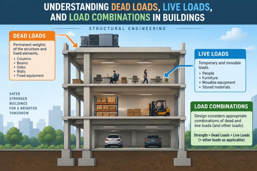

A new floor may look empty when its concrete is poured, but a structural engineer already sees a crowd: the slab itself, finishes, partitions, people, furniture, equipment, snow on the roof, and wind pressing against the façade. Every one of those actions must find a safe path to the ground.
That hidden accounting is why a building can feel calm and ordinary while carrying enormous forces. A classroom, apartment, warehouse, or roof terrace is not designed for a single “weight.” It is designed for a changing collection of loads that act at different times, in different locations, and with different levels of uncertainty.
Confusing these loads can lead to inefficient designs, unexpected deflection, cracking, or—at the serious end—insufficient strength and stability. The goal is not to make every member as large as possible. It is to make a structure reliably resist realistic demands with appropriate safety margins.
Dead loads, live loads, and load combinations are the language used to do that. Once the distinctions are clear, many engineering decisions—from slab thickness to column size—become easier to understand.
🧭 Loads Are Actions, Not Just Weights
In structural engineering, a load is an action that produces force, deformation, stress, or movement in a structure. Gravity loads are usually the first examples, but loads can also arise from wind, earthquakes, temperature changes, soil pressure, water, and construction activity.
Weight acts vertically because of gravity, yet its structural effect depends on where it is placed and how it is supported. A person standing at the center of a floor, for example, may create a different bending effect than the same person standing near a support.
Engineers convert physical conditions into idealized loads that can be analyzed. This model is never a perfect copy of reality; it is a careful representation intended to capture the actions that govern design.
🏢 The Load Path: Following Force to the Ground
A building is safe only when every load has a continuous load path. For a typical floor, gravity loads travel from the slab to beams or walls, then to girders or columns, into foundations, and finally into the supporting soil or rock.
Imagine placing a stack of books on a table. The books load the tabletop, the tabletop transfers force into the legs, and the legs transfer it to the floor. Remove a leg or weaken a connection, and the intended path changes.
Load classification helps engineers quantify what enters that path. Load combinations then test whether each part of the path has enough capacity under credible, sometimes unfavorable, situations.
🧱 What Dead Load Means
Dead load is the permanent gravity load from building components and other fixed items. It includes the self-weight of structural members such as slabs, beams, columns, walls, bracing, and foundations.
It also commonly includes permanently attached nonstructural materials: roofing, floor screeds, ceiling systems, cladding, fixed finishes, and certain fixed building services. A dead load generally remains in place for the building’s life, even though renovations can alter it.
Dead load is sometimes called permanent load. “Permanent” does not mean perfectly known; it means its presence and location are relatively stable compared with occupancy loads.
📦 Typical Components of Dead Load
Dead-load estimates begin by listing actual layers and components rather than assigning one vague number to an entire floor. This is especially useful when materials change across a building.
- Reinforced concrete or steel floor framing
- Concrete topping, screed, tile, carpet, or other floor finishes
- Roof deck, insulation, waterproofing, and ceiling assemblies
- Exterior walls, façade panels, glazing support systems, and parapets
- Fixed partitions and permanently installed mechanical or electrical equipment
Some items require judgment. A demountable partition system may be treated differently from a masonry wall that is clearly permanent. The design basis should state the assumption so later changes can be reviewed.
⚖️ Estimating Self-Weight
Self-weight is found from material unit weight multiplied by volume. For a uniform slab, its thickness and plan area establish the volume; its material density converts that volume into weight.
In preliminary work, engineers may use typical material properties and allowance values. As the design develops, those assumptions should be checked against actual thicknesses, product data, reinforcement, service zones, and architectural details.
A small underestimate repeated across many floors can materially affect columns and foundations. Conversely, excessive conservatism can increase member sizes, embodied material, cost, and seismic mass.
🧰 Superimposed Dead Loads
The structural frame’s own self-weight is only one part of permanent gravity demand. Superimposed dead load refers to permanent weight added on top of the primary structure, such as finishes, ceilings, fixed partitions, and building services.
This distinction is practical because a slab’s own weight may be generated automatically by analysis software, while finishes and partitions must be entered separately. Forgetting one category can make an apparently complete model unconservative.
It also matters during renovation. Replacing lightweight finishes with stone, adding a raised floor, or installing heavy fixed equipment changes the superimposed dead load even when the original frame remains untouched.
🚶 What Live Load Means
Live load is a variable gravity load associated with the use and occupancy of a space. People, movable furniture, stored goods, movable partitions in some applications, and portable equipment are familiar examples.
Unlike dead load, live load can move, appear only occasionally, or concentrate in one area. A library stack aisle, a crowded assembly space, and a sparsely occupied office do not place the same demands on their floors.
Design live loads are not forecasts of the exact weight present at every moment. They are code-based or project-specific representations of reasonably expected occupancy and use, with provisions intended to manage uncertainty.
🏠 Occupancy Changes the Design Demand
A floor’s intended use is central to live-load selection. Residential rooms usually have different loading expectations from offices, corridors, garages, storage rooms, industrial platforms, or public assembly areas.
Storage is particularly sensitive because materials can be both heavy and sustained. A space initially planned as light office accommodation may not be suitable for dense records, packaged goods, or equipment simply because it has open floor area.
When a building changes use, the structural implications should be assessed before the new occupancy begins. The architectural label on a room is not enough; engineers need to understand what will actually be placed there and how it will be used.
📍 Uniform Loads and Concentrated Loads
Loads are represented according to how they are distributed. A uniformly distributed load spreads over an area or length, such as people and desks dispersed over an office floor. A concentrated load acts over a small region, such as a heavy safe, machine support, or wheel.
Both checks can matter. A slab may be adequate for the overall average load but vulnerable to local bending, punching shear, or bearing beneath a concentrated item.
Real loads are never mathematically perfect points or perfectly uniform sheets. Idealizations are used because they reproduce the relevant structural effect with practical accuracy.
🛋️ Furniture Is Not Always a Minor Detail
Most ordinary furniture is already contemplated by the applicable occupancy live load. The concern begins when an item is unusually heavy, tightly supported, or not consistent with the intended use.
Consider a hypothetical archive cabinet placed on four small feet. Its total weight may be manageable for the room, yet each foot can create a high local reaction. The engineer may need to review slab thickness, reinforcement, support location, and whether a load-spreading base is appropriate.
The same principle applies to aquariums, compact filing systems, medical equipment, server racks, and temporary event installations. “It fits through the door” is not a structural check.
🌨️ Roof Loads Are More Than Roof Weight
Roofs carry their permanent construction weight, but they may also be subject to variable environmental loads. Snow can accumulate, drift against taller elements, or form uneven patterns. Rainwater can pond if drainage is obstructed or if deflection changes the roof slope.
Maintenance workers and equipment can also govern parts of a roof. Green roofs, photovoltaic arrays, rooftop plant, and future equipment replacement need clear classification as permanent or variable actions as appropriate.
Roof loading depends strongly on climate, geometry, drainage, exposure, and local requirements. It should not be assumed that a roof designed for one region or configuration is automatically suitable for another.
🌬️ Wind Is a Different Kind of Variable Load
Wind does not simply add weight downward. It pushes laterally on walls and can pull upward on roof edges and cladding. Its magnitude and distribution depend on wind speed, building height, shape, terrain, openings, and local pressure effects.
For the main structure, wind can create overturning, sway, and uplift. For façade connections and roof coverings, localized suction can be more critical than the overall building force.
Wind may occur while a floor is occupied, but the maximum design values of every action are not necessarily assumed to occur simultaneously. This is one reason load combinations are necessary.
🌎 Seismic Actions Come From Mass and Motion
Earthquake loading is an inertial effect: when the ground accelerates, the building’s mass resists that motion. Dead load is therefore especially influential because permanent mass is always present; a defined portion of occupancy load may also be relevant depending on the design situation and governing rules.
Seismic design considers more than strength. Buildings must have an understandable lateral-force-resisting system, ductile detailing where required, stable connections, and a load path that carries forces through diaphragms, frames, walls, and foundations.
A heavier building is not automatically unsafe, but added permanent weight can increase seismic demand. This creates a useful reminder: structural choices affect several hazards at once.
🔄 Why Loads Must Be Combined
Designing for dead load alone misses occupancy and environmental actions. Designing for the full maximum value of every possible load at the same instant can be unrealistically severe. Load combinations provide structured scenarios that balance these realities.
A combination adds and factors selected actions to represent a design condition. One combination may emphasize gravity and occupancy; another may emphasize wind uplift; another may pair permanent load with earthquake effects and reduced accompanying variable actions.
The exact combinations and factors come from the governing building code and project basis of design. They are not interchangeable rules of thumb, and they vary by jurisdiction, material system, and design method.
🛡️ Load Factors and Safety Margin
In strength-based design, loads are often multiplied by load factors. A factor greater than one increases an action to account for uncertainty in its magnitude and for the possibility of unfavorable conditions.
Different actions receive different treatment because they have different variability and predictability. Permanent material weight can often be estimated more consistently than occupancy, weather, or certain environmental effects.
On the resistance side, member capacity is also adjusted according to the design framework. The result is a coordinated reliability approach, not a claim that an individual load factor alone guarantees safety.
📏 Strength Design and Serviceability Design
Structural performance is checked at more than one level. Strength checks ask whether members, connections, and foundations can resist factored forces without failure. Serviceability checks ask whether the building performs acceptably in normal use.
Serviceability may include deflection, vibration, cracking, drift, settlement, ponding behavior, or damage to finishes and partitions. A floor can be strong enough to avoid collapse but still feel bouncy or allow finishes to crack.
Service-level combinations often use unfactored or differently modified loads, depending on the applicable design rules. Keeping strength and serviceability models distinct prevents a common source of confusion.
🧮 A Simple Beam Example
Suppose a hypothetical beam supports a floor area. The floor system, finishes, and fixed ceiling create a permanent distributed load. People and movable furniture create a variable distributed load, while a temporary piece of equipment may add a concentrated load.
The engineer first determines the tributary width—the portion of floor that delivers load to that beam—and converts area loads into a line load. The beam analysis then produces reactions, shear forces, and bending moments for each load case.
Relevant load combinations combine those effects. The controlling combination for bending may differ from the one controlling support reaction, uplift, deflection, or connection design. There is no universal “worst load” for every check.
📐 Tributary Area Connects Floors to Members
Tributary area is a convenient method for assigning floor or roof load to a supporting member. It is the area whose load is considered to flow to that member, based on the framing layout.
For a simple interior beam between parallel beams, the tributary width is often taken as half the spacing to the adjacent beam on each side. Multiplying that width by the beam span converts an area-based load into the beam’s tributary load.
The method is an idealization. Irregular geometry, two-way slab action, transfer conditions, openings, and stiffness differences may require more refined analysis.
🏗️ Load Patterns Can Govern Continuous Members
In a simple span, a uniform gravity load produces a familiar positive bending pattern. Continuous beams and slabs behave differently because load on one span affects moments in neighboring spans.
For variable live load, placing load on every span is not always the most unfavorable arrangement. Alternate spans or selected loaded areas can increase negative moments over supports or produce larger reactions in a particular column.
Structural analysis software can evaluate many patterns, but the engineer must define the correct cases and understand the output. A polished model cannot compensate for missing or incorrectly patterned live load.
⬇️ Downward Loads and Uplift Work Together
Gravity loads are often helpful when wind creates uplift or overturning. The permanent weight of a roof or building can resist a tendency for supports to lift, while connections and foundations provide the remaining restraint.
However, live load should not automatically be counted as stabilizing. Occupancy may be absent when a severe wind event occurs, and code combinations generally reflect that uncertainty.
This is especially relevant for canopies, light roofs, solar arrays, tall narrow structures, and foundations subject to overturning. Checking only downward reactions can hide a critical tension demand.
🏗️ Construction Loads Are Temporary but Real
A partially completed building can experience conditions that do not occur after completion. Fresh concrete, stacked materials, shoring, formwork, construction equipment, and incomplete lateral bracing can create demanding temporary load cases.
For example, a newly cast concrete floor may support construction materials before the concrete has reached its intended strength, while shoring transfers load into lower levels. The sequence matters as much as the final geometry.
Temporary works and construction-stage engineering deserve deliberate planning. Assuming the completed-building model covers every construction condition is a potentially costly mistake.
🔧 Equipment Loads Need Better Questions
When equipment is proposed, asking for total weight is only the start. Engineers also need support locations, footprint, operating loads, vibration, moving parts, anchorage forces, maintenance access, and whether the item will be replaced by a heavier unit.
Mechanical units may impose point reactions at curbs or rails. Elevators, cranes, and rotating machinery can introduce dynamic effects. Tanks introduce fill levels, fluid movement, and potentially different empty and full conditions.
Clear manufacturer information and early coordination are more efficient than discovering late in construction that the support frame needs substantial strengthening.
🧱 Partitions Can Change More Than Layout
Partition walls may look architectural, but their weight can be a meaningful floor load. Their effect depends on wall construction, height, location, and whether the framing system can distribute that load across a wider area.
Light, relocatable partitions are sometimes represented through a distributed allowance. Heavier masonry or glazed partitions are more often treated as line loads at known locations. The appropriate approach depends on the design rules and actual layout.
Moving a partition onto the middle of a long-span slab can change deflection and cracking behavior. Coordination between structural and architectural teams should continue beyond the first layout.
🧩 Connections Must Carry the Same Story
A member may have adequate calculated strength, yet its connections can still govern. Beam-to-column connections, joist seats, anchors, welds, bolts, slab reinforcement around supports, and foundation ties all need forces derived from the same load cases and combinations.
Discontinuities are where load paths often become less obvious: a transfer girder, a façade bracket, an offset column, or a roof collector. These locations deserve explicit free-body diagrams and connection checks.
Good structural design is consistent from roof covering to soil. A force should not disappear merely because the analysis model ends at a member centerline.
🖥️ What Software Calculates—and What It Cannot Know
Analysis programs efficiently calculate forces, deflections, reactions, and mode shapes for complex structures. They can also organize many combinations and reveal patterns that would be tedious to calculate by hand.
But software cannot independently verify an assumed finish weight, recognize a future storage use, or decide that a model’s supports and releases are physically realistic. Those are engineering judgments.
A useful practice is to hand-check a representative beam, tributary load, total building weight, and reaction. Large discrepancies between a simple estimate and a model should be understood, not ignored.
🚫 Common Load-Definition Mistakes
Many load problems begin before analysis. They arise from incomplete information, hidden assumptions, or assigning an action to the wrong category.
- Omitting finishes, façade weight, ceilings, or permanent services from dead load
- Using a generic live load without confirming the intended occupancy
- Applying area load where a line or point load is needed
- Missing localized equipment reactions or wheel loads
- Counting nonstructural weight twice, or allowing software to double-count self-weight
- Ignoring uplift, patterned loading, construction stages, or a change of use
- Combining loads with factors from an inapplicable code or design method
These errors are not fixed by adding arbitrary thickness everywhere. The remedy is a traceable load schedule, coordinated information, and targeted verification.
📝 Building a Reliable Load Schedule
A load schedule documents the actions used in design, their magnitudes, locations, basis, and classification. It turns scattered assumptions into information that another engineer, reviewer, or future renovation team can follow.
| Load category | Typical source | Key question |
|---|---|---|
| Dead load | Structure, finishes, fixed systems | What remains permanently attached? |
| Live load | Occupants, furniture, movable items | How is the space actually used? |
| Environmental load | Wind, snow, rain, seismic action | What site and geometry conditions apply? |
| Construction load | Shoring, wet concrete, stored materials | What occurs before completion? |
The schedule should identify unusual assumptions, such as future equipment allowances or designated storage zones. This is valuable documentation, not paperwork for its own sake.
🔍 Reviewing an Existing Building
Assessing an existing building requires extra care because drawings may be incomplete, materials may differ from assumptions, and renovations may have altered the load path. Field observation, measurements, material investigation, and records review may all be needed.
Capacity cannot be inferred simply from member size. Reinforcement, connection details, corrosion, deterioration, prior damage, support conditions, and applicable historical design practices can affect the conclusion.
When proposed loads exceed the original intended use, options may include redistribution, local strengthening, new supports, lighter equipment, or operational limits. A qualified structural engineer should define the assessment scope and limitations.
🤝 Coordination Prevents Late Structural Surprises
Architects, mechanical engineers, electrical engineers, contractors, owners, and facility teams all influence loading. A roof unit, suspended pipe rack, façade material change, or storage plan can alter structural demand.
The most useful coordination questions are concrete: What does it weigh? Where are its supports? Is it permanent? Does it move, vibrate, or need replacement access? What happens during installation?
Early answers let the structural system accommodate real requirements efficiently. Late answers often lead to awkward transfer steel, reinforcement changes, schedule disruption, or restricted use.
✅ The Core Principle: Design for Credible Conditions
Dead loads describe what the building continuously carries. Live loads represent changing use. Environmental and construction loads address conditions that may be intermittent but can be decisive. Load combinations bring these actions together in code-defined design scenarios.
The essential task is not memorizing labels or applying factors mechanically. It is understanding the physical source of each action, tracing it through the structure, and checking both strength and usable performance.
When assumptions are visible, occupancy is understood, and load paths are continuous, calculations become more than numbers on a page. They become a reasoned argument that the structure can perform as intended.
A sound building design begins with a complete, realistic picture of the loads it must carry—and where those loads must go. 🏗️📐✅