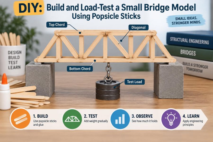

A bridge model can look convincing on a desk and still fail the moment a small weight is placed at midspan. That contrast is what makes this classroom-scale project so valuable: it turns an ordinary craft material into a practical lesson about how structures carry load.
Perhaps you have seen a popsicle-stick bridge bend, twist, or suddenly unzip at one glue joint. Those failures are not simply bad luck. They reveal forces, weak connections, poor bracing, and material limits that engineers must anticipate in full-size bridges too.
Building and testing a small bridge does not reproduce every detail of real bridge design. Wood sticks are not steel girders, loads are simplified, and the scale effects are significant. But the model provides an accessible way to observe tension, compression, bending, buckling, and load paths with your own hands.
This guide focuses on making a controlled experiment rather than merely a decorative bridge. You will define the rules, build consistently, load safely, document what happens, and use the result to improve the next design.
🧭 Start With a Clear Engineering Question
A useful project begins with a question that can be tested. For example: Which truss arrangement carries the greatest central load for the same span and material allowance? That question is more informative than asking which bridge “looks strongest.”
Choose one main performance measure. Maximum load before failure is common, but you could also compare stiffness, material efficiency, or reliability across repeated models.
- Maximum load: the highest supported load before a defined failure.
- Stiffness: how little the bridge deflects under a chosen load.
- Efficiency: supported load divided by bridge mass or number of sticks.
- Repeatability: whether similar bridges behave similarly.
📏 Define the Design Brief Before Cutting
Write down the constraints before construction. A fair bridge test needs a fixed clear span, support arrangement, loading location, permitted materials, and a definition of failure.
For a manageable model, use a span such as 300 mm between bearing points. Require the bridge to sit on the supports without being taped down, and apply a vertical load at the middle of the deck.
Decide whether the bridge must carry a small cart, leave clearance beneath it, or fit inside a maximum width and height. Constraints force trade-offs—the everyday reality of structural design.
🪵 Gather Materials That Behave Consistently
Select straight, dry popsicle sticks with no obvious cracks, severe warping, or loose splinters. Craft sticks vary in density and grain direction, so visual sorting reduces one avoidable source of variation.
- Popsicle sticks from the same package where possible
- Wood glue suitable for interior craft work
- Ruler, pencil, and a square
- Craft knife or small saw, used with appropriate supervision
- Clamps, binder clips, or masking tape for holding joints while glue cures
- Digital kitchen scale or known masses for loading
- Two stable support blocks of equal height
- A loading plate or small container to distribute the test load
Adhesive is part of the structure. Changing glue type, cure time, or joint preparation can change the outcome, so keep those choices consistent when comparing designs.
🦺 Set Up Safe Building and Testing Practices
Use cutting tools on a protected surface and cut away from hands. Follow the adhesive manufacturer’s safety guidance and provide ventilation where required.
During testing, keep faces and hands away from the bridge and from the load directly above it. A brittle stick can snap sharply, and a falling mass can damage a table or toes. A shallow tray, box, or clear shield around the loading area can help contain fragments.
This is a demonstration of structural principles, not a method for assessing a bridge intended to carry people, vehicles, or real service loads.
🌉 Choose a Bridge Type That Fits the Experiment
A simple beam bridge is the easiest starting point: two or more longitudinal members span between supports, with a deck on top. It quickly demonstrates bending, but a single thin stick over a long span is usually flexible.
A truss bridge uses straight members arranged in triangles. Its geometry can move much of the load through axial forces—tension and compression—rather than relying only on bending resistance.
| Configuration | What it demonstrates | Typical challenge |
|---|---|---|
| Beam bridge | Bending and deflection | Large midspan sag |
| Triangular truss | Axial force and triangulation | Accurate joints are essential |
| Box or through truss | Three-dimensional stability | More alignment and bracing work |
| Arch-like form | Compression and horizontal thrust | Support restraint is difficult to model |
🔺 Understand Why Triangles Stabilize a Frame
A four-sided frame made from pin-like joints can change shape into a parallelogram without changing member lengths. A triangle cannot do that unless a member stretches, shortens, bends, or a joint rotates.
Diagonal members turn a rectangular side frame into a sequence of triangles. This is why trusses, roof bracing, tower frames, and temporary scaffolds so often use diagonal patterns.
Triangulation does not make every bridge automatically strong. A triangle with weak glued ends or a slender compression member can still fail, but the geometry gives the load a more controlled path.
➡️ Map the Load Path
A load path is the route forces take from the point of loading to the ground. In a model bridge, a central load may pass from the loading plate into cross members, then into side trusses, then through end joints to the supports.
At each transition, ask: is there wood directly under the force, or is the load relying on a fragile glue edge? A visible load path usually produces a more reliable model than a design with isolated decorative members.
Imagine pressing a book onto a cardboard box. If the force reaches the corners through continuous folds, the box performs better than if it first passes through a loose flap. Your bridge needs that same continuity.
↕️ Identify Tension and Compression Members
When a simply supported bridge bends downward under a central load, the upper part tends to shorten and the lower part tends to lengthen. In an ideal truss under similar loading, the top chord is often primarily in compression, while the bottom chord is often primarily in tension.
Compression pushes material together. Tension pulls it apart. Wood sticks usually tolerate modest tension well when the member and its joint are intact, while slender compression members are often controlled by buckling.
Force directions in a real truss depend on geometry, support conditions, and where the loads are applied. Treat these rules as useful expectations, then compare them with the observed deformation.
📐 Select Sensible Overall Proportions
A very shallow truss has little separation between its top and bottom chords, so it must develop larger chord forces to resist the same bending effect. Increasing truss depth can improve structural efficiency.
However, making a model taller can make it more susceptible to sideways instability if it lacks cross-bracing. A practical starting point is a bridge whose truss depth is visibly substantial relative to its span, rather than a nearly flat side frame.
Keep two side trusses parallel and separated by a stable deck width. The resulting three-dimensional form is often more important than adding random extra sticks to one side.
✏️ Draw a Full-Size Template
Draw one side truss at full scale on paper before gluing. Mark the support locations, panel points, chord lines, and diagonal endpoints. A repeating panel layout makes comparison and troubleshooting easier.
Place wax paper or another glue-resistant barrier over the drawing, then assemble directly over it. The template keeps the first truss straight; use the same template for the second one so their geometry matches.
Do not glue the bridge directly onto ordinary paper. Glue can wick into it, making removal messy and potentially damaging the joints.
🧩 Choose a Truss Pattern Intentionally
For a first build, a Warren-style pattern of repeating triangles is simple and uses relatively few member directions. A Pratt-style arrangement, with diagonals sloping toward the center, offers a useful comparison and is commonly discussed in bridge engineering.
The goal is not to copy a named truss perfectly. It is to use a regular, triangulated arrangement in which each member meets a joint node—the location where forces are intended to transfer.
Avoid diagonals that stop midway along another stick unless you provide a proper joint. A connection that merely touches a chord can introduce bending and peel stresses that the simple truss idealization does not capture.
🧱 Build Strong Chords, Not Just Strong Diagonals
Chords are the long top and bottom members of a truss. Because they run nearly the full length, their continuity matters greatly. A weak splice near midspan can become the controlling failure point.
If a chord must be made from multiple sticks, stagger the splices rather than aligning them across every laminated layer at one section. Overlap pieces sufficiently and keep the joint area flat so adhesive can develop a broad bond.
Adding a second layer to a compression chord can improve its resistance to bending and buckling, but added material should be placed where it addresses an identified weakness.
🧷 Make Joints With Real Bearing Area
Glue joints fail when the adhesive is asked to bridge large gaps, peel apart, or transfer force through a tiny contact patch. Trim members so they meet neatly and sit in the same plane.
Use enough glue to wet the contact surfaces, but do not create thick puddles. Excess adhesive adds mass, cures slowly, and does not compensate for poor fit.
Where permitted by your rules, small gusset plates cut from thin card or wood can spread force around a node. If you use gussets, apply them consistently to comparable joints and include their mass in the evaluation.
🧼 Prepare Wood Surfaces Before Gluing
Lightly sanding a glossy or contaminated surface can improve contact, especially at cut ends. Remove dust before applying adhesive.
End grain can absorb glue rapidly, leaving a dry-looking joint. For a critical end-grain connection, a light first coat followed shortly by the main adhesive application may help, provided it is compatible with the glue instructions.
Do not rely on a joint’s appearance alone. A shiny bead around the edge says less about strength than close-fitting wood surfaces held in position during curing.
🗜️ Clamp Without Distorting the Geometry
Clamping pressure holds surfaces together while the adhesive cures, but excessive pressure can squeeze out too much glue or bend a lightweight assembly. Binder clips, pins around the outside of a template, and small weights are often adequate.
Check the truss from above before leaving it to cure. A slight twist introduced at this stage is difficult to remove later and can make a bridge lean under load.
Allow the adhesive to cure for the full time recommended for structural handling. Testing a joint that is only surface-dry measures rushed construction more than it measures your design.
🛤️ Connect the Two Side Trusses
Two strong side trusses do not automatically form a strong bridge. They need transverse members—cross members that connect side to side—so the applied load reaches both trusses.
Install cross members at panel points where possible. These are natural force-transfer locations and reduce the chance of loading a chord between joints.
Measure the spacing at both ends and near the center. If the side trusses converge or diverge, the bridge may twist as soon as load is applied.
🧊 Add Lateral Bracing Against Twist
Lateral bracing runs across the top and/or bottom plane of the bridge, often diagonally. It prevents the compression chord from moving sideways and helps the two trusses act as one three-dimensional system.
A top chord that appears strong in its own vertical plane may buckle sideways if it has no restraint. This is a small-scale version of lateral-torsional instability: bending and twisting interact when a compression region is unbraced.
Use X-bracing or diagonal ties across the top plane when the bridge allows it. Keep the bracing symmetrical so it restrains rather than introduces an unwanted twist.
⚖️ Keep Mass and Material Use Honest
More sticks can raise capacity, but they also make the bridge heavier and may obscure whether the geometry itself improved. If your comparison is about efficient design, weigh each completed model.
A simple efficiency indicator is the failure load divided by bridge mass. It is not a universal measure of structural merit, but it can prevent a heavily reinforced design from being called “better” without qualification.
Record the stick count as well. Two bridges of equal mass can still differ because one uses material in long continuous chords while the other concentrates it at joints.
📋 Create a Test Plan Before the Bridge Is on the Supports
Decide in advance what you will measure and how often. This protects the experiment from changing the rules after seeing an unexpected result.
- Bridge identification and design sketch
- Clear span, width, depth, and mass
- Adhesive and cure duration
- Load increment and loading interval
- Midspan deflection at each increment
- First visible damage and final failure mode
Define failure clearly. It might be a broken member, permanent visible distortion, a joint separation, or deflection beyond a specified limit. “It looked bad” is too subjective for useful comparison.
🏠 Prepare Stable, Level Supports
Set two solid supports on a stiff, level surface and verify their spacing with a ruler. The bridge ends should bear evenly, not perch on a corner or a stray glue blob.
Simple supports are a reasonable approximation for a basic test: the bridge can rotate slightly at its ends while vertical reaction forces carry load to the table. Do not clamp the ends unless that restraint is part of the stated design brief.
Uneven supports can cause one truss to carry more load than the other. That may produce a misleading failure that reflects the setup rather than the bridge.
🎯 Apply the Load at a Defined Location
For a central point-load test, use a small loading plate, block, or container placed at the middle of the span. The plate should contact both side trusses through cross members, rather than pressing directly onto a single fragile stick.
Add load in small, known increments. A container receiving identical coins, washers, or measured sand portions can work, as long as you record the total mass and do not add items abruptly.
Apply the load gently. Dropping a mass creates impact effects, which are different from the intended static test and can cause premature failure.
📉 Measure Deflection, Not Only Collapse
Deflection is the vertical movement of the bridge under load. Place a ruler behind the center of the bridge or use a fixed pointer beneath the deck to observe movement relative to a stationary reference.
A bridge that carries a load but sags substantially may not meet a serviceability requirement in a real project. Structural performance is not only about avoiding fracture; excessive movement can damage finishes, alarm users, or change load distribution.
For each load step, note whether the bridge returns to its original position after unloading. Residual sag suggests permanent damage, joint slip, or material yielding/crushing.
👀 Watch for Early Warning Signs
Failure often begins before the final break. Listen for soft cracking sounds, watch for a joint opening, and look along the top chord for a slight sideways bow.
Use a phone to record a side and top view if possible. Slow-motion review can reveal whether a diagonal buckled first, a splice opened, or the entire bridge twisted before one stick fractured.
Stop the test if the load becomes unstable or the setup is no longer safe. Capturing a dramatic collapse is never worth an uncontrolled falling object.
💥 Classify the Failure Mode
Give the failure a specific name. That turns an observation into a design lesson.
| Observed behavior | Likely mechanism | Potential design response |
|---|---|---|
| Top member bows sideways | Compression buckling | Shorten unsupported length or add lateral bracing |
| Joint peels open | Poor fit or eccentric force transfer | Increase bearing area and improve alignment |
| Bottom chord separates | Tension failure at splice or joint | Stagger splices and reinforce the connection |
| Bridge rotates as a whole | Insufficient cross-bracing or uneven loading | Stiffen the box form and check supports |
| Local deck stick breaks | Concentrated load on a weak cross member | Distribute load at panel points |
🧮 Use Simple Calculations With Appropriate Caution
If you apply a single central load, a symmetric bridge has approximately half the vertical load reaction at each support before major damage occurs. This is a useful equilibrium check: total upward support reaction balances total downward load.
For an ideal simply supported beam with a centered load P over span L, the maximum bending moment is often written as M = P L / 4. The model’s truss is more complicated than a single beam, but the relationship explains why longer spans are generally more demanding under the same load.
These calculations assume simplified support and loading conditions. They do not predict the exact capacity of a hand-built model with variable timber and glue joints.
🔁 Compare One Variable at a Time
If you change the truss pattern, chord thickness, glue, span, and bracing all at once, you will not know what caused the new result. A better experiment changes one meaningful variable while holding the rest as constant as practical.
For example, build two bridges with the same span, stick count, cross members, and curing time. Add top lateral X-bracing to only one. Compare deflection under the same load sequence and note the failure behavior.
Handmade models naturally vary. Repeating a design more than once gives a more trustworthy impression than drawing conclusions from a single bridge.
🚫 Avoid Common Shortcuts That Weaken Models
Some choices save minutes during assembly but cost meaningful structural performance during testing.
- Decorative diagonals: members that do not reach proper joints may contribute little useful force transfer.
- Aligned splices: stacking every chord joint at one cross-section creates a predictable weak plane.
- Uncured adhesive: early testing can turn a glue-time issue into a false design conclusion.
- Missing top bracing: strong-looking side trusses can still roll or buckle sideways.
- Off-center loading: a misplaced load makes one side carry more than the other.
- Huge load jumps: they hide the deflection history and introduce impact.
🛠️ Improve the Design From Evidence
Use the failure mode to select the next change. If a compression diagonal buckled, adding material to a tension joint is unlikely to solve the main problem. Instead, shorten the diagonal’s unbraced length, reorient the arrangement, or increase its section.
If the model failed at a joint while members remained straight, focus on fit, overlap, gusseting, and how forces enter the node. If it twisted, inspect the spatial bracing and whether both side trusses received load evenly.
The best redesigns are targeted. They preserve features that worked and address the first critical weakness, rather than making every member thicker.
🧪 Extend the Project With Meaningful Variations
Once the basic procedure works, use it to investigate a focused structural question. Keep a careful record so each variation remains interpretable.
Useful comparison ideas
- Compare a beam bridge and a triangulated truss at equal span and similar mass.
- Compare top-chord lateral bracing with no lateral bracing.
- Compare a shallow truss with a deeper truss using similar panel spacing.
- Compare staggered chord splices with aligned splices.
- Move the load from midspan toward one support and observe changing behavior.
These are hypothetical experiments, not substitutes for full structural analysis. Their value lies in making a specific mechanism visible.
📝 Present Results Like an Engineer
A clear report includes the design brief, dimensioned sketch, material list, construction notes, test setup, load-deflection record, and photos taken before and after failure. Include at least one image showing the support and loading arrangement.
Separate observation from interpretation. “The top chord moved sideways near the center” is an observation. “The top chord likely experienced lateral buckling because it lacked restraint” is an interpretation supported by that observation.
State limitations honestly: stick properties vary, glue quality differs between joints, loads may not be perfectly centered, and small-scale behavior cannot be directly scaled to real bridges.
🌍 Connect the Model to Full-Scale Structural Practice
Real bridge engineering adds traffic patterns, wind, temperature movement, fatigue, corrosion, foundations, construction sequencing, inspection access, and codes. Engineers also use calculations, computer models, material testing, and conservative safety margins.
Yet the central habits are recognizably similar: define loads, trace their path, provide stability in all directions, detail connections, and check how a structure responds before failure. A modest sticks-and-glue model makes those habits tangible.
Models are especially useful for communication. A team can often spot an unclear load path or missing brace in a physical model before debating equations.
🏁 The Core Lesson: Direct Forces Deliberately
A successful popsicle-stick bridge is not the one with the most adhesive or the most elaborate silhouette. It is the one whose geometry, members, joints, and bracing work together to deliver load safely to its supports.
Build with a stated purpose, test with controlled increments, and let the failure teach you where the force path was weak. That cycle—design, observe, revise—is the lasting engineering lesson.
When you can explain where the load goes, what each member does, and why failure began where it did, you have learned far more than how to make a bridge hold weight. 🏗️🪵📐