
A flat concrete ceiling can make a building feel simple: a smooth slab, slender columns, and open space below. Yet where each column meets the slab, a highly concentrated structural problem is taking place.
Floors in offices, apartments, parking structures, and hospitals often carry loads through slabs directly into columns. Most of the slab may appear calm and lightly stressed, while a small zone around a column works intensely to transfer the entire floor load downward.
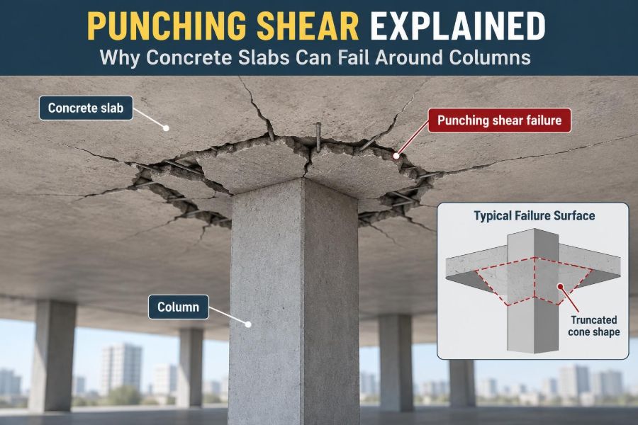
If that zone fails in punching shear, the column can appear to punch a plug-like piece out of the slab. The failure may happen with limited visible warning, which is why engineers treat it as a critical safety check rather than a minor detail.
Understanding punching shear connects basic load paths, concrete behavior, reinforcement detailing, construction quality, and structural robustness. It also explains why some columns have thickened slab heads, drop panels, or carefully placed shear reinforcement.
🏢 What Punching Shear Means
Punching shear is a localized shear failure that can occur when a concentrated support or load acts on a concrete slab. In floor systems, the common case is a column pushing upward into the underside of a slab while gravity loads push the slab downward.
Rather than bending gradually over a wide area, the slab can crack along a roughly closed surface around the column. The separated central portion resembles a truncated cone or pyramid, depending on the geometry and how the failure develops.
🧱 The Load Path Through a Flat Slab
A flat slab transfers floor loads to columns without deep beams framing every bay. The slab collects its own weight, finishes, partitions, people, furniture, and other imposed loads, then delivers reactions to each column.
Near a column, a large reaction must pass through a relatively thin slab depth. That concentration is the fundamental reason punching shear is a governing design issue in many flat plates and flat slabs.
🔄 Why the Column-Slab Joint Is Different
At midspan between columns, bending usually controls because the slab spans and sags under load. At a column, the slab is supported, bending moments reverse, and shear stresses become much more concentrated.
The critical issue is not simply that the column touches the slab. It is that the column reaction rises rapidly from zero outside the support region to a large force over a short distance. Concrete must spread that force outward through the slab.
📐 A Simple Way to Picture the Mechanism
Imagine pressing a small cookie cutter into a thick piece of clay from below while holding the clay down around it. If the clay cannot resist the inclined tearing action around the cutter, a plug separates.
Concrete does not behave like clay, and real slabs contain reinforcement, aggregate, cracks, and varying stress fields. Still, the analogy captures the key idea: a concentrated force can break out a region around its perimeter rather than bend the whole slab.
📏 The Critical Perimeter
Design checks commonly evaluate shear around a critical perimeter, an imagined closed line surrounding the column. The position and shape of that perimeter depend on the applicable design standard, support geometry, and whether the column is interior, edge, or corner.
Engineers compare the shear demand crossing that perimeter with the slab’s available resistance. The governing perimeter is not always the same for every detail, especially when drop panels, capitals, openings, or shear reinforcement are present.
➗ Shear Stress Is a Useful Design Concept
A simplified average punching shear stress can be thought of as the column reaction divided by the critical perimeter times the effective slab depth. A larger perimeter or greater effective depth spreads the same force through more concrete.
This is a design model, not a claim that stress is perfectly uniform around the perimeter. Actual stress concentrations occur near corners, reinforcement, cracks, and irregular geometry, which is why standards include detailed rules and resistance limits.
📚 Codes Set the Check, Not the Physics
Structural codes provide equations, critical locations, load combinations, strength-reduction factors, and detailing requirements. Different jurisdictions use different standards, so the exact procedure and terminology can vary.
The physical behavior remains the same: concentrated reaction, inclined cracking, and a limited depth available to resist shear. Designers should never mix provisions from different codes casually or substitute a remembered formula for the current governing standard.
🧩 The Shape of a Punching Failure Surface
Cracks associated with punching shear often propagate on an inclined surface extending outward from the column region. In a simplified view, the potential failure surface is wider near one face of the slab than near the other.
The angle is not fixed. It is influenced by aggregate interlock, reinforcement, concrete strength, slab depth, loading history, and cracking. Treating punching as a single neat geometric cone is useful for visualization, but inadequate for detailed assessment.
🪨 What Concrete Contributes
Concrete resists shear through several interacting mechanisms. These include the uncracked compression zone, aggregate interlock across cracks, residual tensile action, and dowel action from reinforcing bars.
Once flexural cracks form and open near a support, some of those mechanisms become less effective. That is why the slab’s punching resistance is tied to cracking, reinforcement ratio, depth, and deformation—not merely its specified compressive strength.
🔩 What Flexural Reinforcement Contributes
Top reinforcement over columns is primarily placed to resist negative bending moments. It also matters to punching behavior because it controls crack widths, deformation, and the ability of the slab to develop its intended load-transfer mechanisms.
More flexural steel is not an unlimited solution. A slab with high bending capacity can still be vulnerable to punching if its depth is inadequate or if the support region is not properly detailed.
📉 Why Failure Can Be Brittle
Flexural failure in a well-detailed reinforced concrete member often develops substantial deflection and cracking before ultimate capacity. Punching shear can be less forgiving because the failure zone is localized and the resistance can drop quickly after a critical crack forms.
“Brittle” does not mean instantaneous in every case, nor does it mean cracks are always invisible. It means the margin between a heavily stressed condition and loss of support can be smaller than engineers want in a primary gravity-load connection.
⚖️ Interior, Edge, and Corner Columns
An interior column has slab extending in all directions, allowing a closed shear perimeter with broad load distribution. Edge and corner columns have less surrounding slab, creating more demanding geometry and often introducing unbalanced moment effects.
| Column location | Typical punching concern | Additional complication |
|---|---|---|
| Interior | High concentrated reaction | Symmetric perimeter, but large tributary area |
| Edge | Reduced effective perimeter | Moment transfer can be significant |
| Corner | Most limited surrounding slab | Two free edges and asymmetrical cracking |
These cases cannot be treated as simple copies of one another. Support location changes both the available resisting region and the way forces flow through the slab.
🌀 Unbalanced Moment Makes the Problem Harder
Columns do not always receive purely concentric gravity reactions. Wind, seismic action, frame action, unequal spans, and lateral drift can transfer unbalanced moment between the slab and column.
That moment causes shear stress to become nonuniform around the perimeter. One side may be more highly stressed than the average calculation suggests, so design methods explicitly address the combined effect of shear and moment transfer.
🏗️ Flat Plates and Flat Slabs
A flat plate is generally a slab supported directly by columns with a uniform thickness. It offers clean soffits and efficient formwork but can be controlled by deflection and punching shear.
A flat slab may include local thickening, such as a drop panel or column capital. Terminology differs by region, but the structural purpose is clear: provide more material and a larger effective shear-resisting zone where the reaction enters the slab.
⬇️ Drop Panels Add Depth Where It Counts
A drop panel is a thickened slab region around a column. Increased effective depth can substantially improve punching resistance because the potential shear surface becomes larger and the slab has more depth to develop internal force transfer.
Drop panels also affect stiffness and negative-moment behavior. Their dimensions, thickness transition, and reinforcement must be designed as a coordinated detail; adding a small thickening without checking its geometry may not solve the governing problem.
🍄 Column Capitals Spread the Reaction
A column capital, sometimes called a column head, flares the top of a column beneath the slab. By enlarging the support area, it can move critical punching checks outward and reduce local stress concentration.
Capitals can be structurally effective but may conflict with architectural ceiling requirements, mechanical services, formwork simplicity, and fire protection details. The best solution is therefore project-specific rather than automatic.
🪜 Shear Reinforcement Is a Targeted Solution
Where slab thickness or support enlargement is impractical, designers may use punching shear reinforcement. Common systems include headed shear studs, stirrup-like assemblies, or other proprietary and code-recognized arrangements.
These elements cross potential inclined cracks and provide additional resistance after concrete cracking. Their layout, anchorage, spacing, outer extent, and compatibility with the selected standard are essential; shear reinforcement is not simply extra steel placed near a column.
📍 The Outer Perimeter Still Needs Checking
Shear reinforcement can shift the critical location away from the column. At the outer edge of the reinforced zone, the slab must still have adequate concrete resistance because a punching-type failure may occur just beyond the last row.
This is a frequent conceptual mistake: strengthening the immediate column zone while overlooking the transition to ordinary slab. A complete design checks all required perimeters and all applicable modes.
🚪 Openings Can Interrupt the Force Flow
Openings for pipes, ducts, drains, stairs, and services can remove concrete that would otherwise participate in the punching perimeter. Their effect is especially significant when they lie close to a column.
An opening is not judged only by its area. Its position relative to the column and critical perimeter matters because it can interrupt the shortest and most effective load paths around the support.
🧭 Transfer Slabs Face Larger Concentrations
Transfer slabs support columns or walls that do not continue directly to the foundation. They may carry unusually large concentrated reactions and can be thick, heavily reinforced, and congested.
Punching shear in transfer structures demands careful analysis beyond a routine floor-slab check. Load sequencing, stiffness, construction joints, local bearing, strut-and-tie behavior, and interaction with nearby supports may all matter.
🏠 Foundation Slabs Have the Same Basic Risk
Punching shear is not limited to elevated floors. Footings can punch around columns under upward soil pressure, and mats can face concentrated support reactions or column loads depending on the load path being considered.
The direction of loading changes in the mental picture, but the mechanics are analogous: a concentrated force must be transferred through a finite thickness of reinforced concrete without forming a breakout surface.
🧪 Material Strength Is Only One Variable
Higher-strength concrete may improve some aspects of punching resistance, but it does not remove the need for depth, reinforcement, and sound detailing. Concrete strength gains do not always translate proportionally into a safe or economical punching solution.
Engineers also consider aggregate characteristics, lightweight versus normal-weight concrete where applicable, curing, actual in-place quality, and the code limits placed on calculated strength. A stronger mix cannot compensate for a missing load path.
🛠️ Construction Quality Can Change the Detail’s Performance
Dense reinforcement around columns makes placement and consolidation difficult. Poorly compacted concrete, misplaced top bars, inadequate cover, unintended construction joints, or incorrectly installed shear studs can reduce the performance assumed in design.
Inspection should focus on what makes the connection work: slab thickness, support dimensions, reinforcement position, stud layout, embedment, concrete placement, and curing. The as-built detail must match the engineered detail, not merely resemble it.
🔍 Warning Signs During Assessment
Cracks near columns deserve professional attention, especially when accompanied by increased deflection, new serviceability problems, water leakage through cracks, or changes after altered loading. Cracks alone do not diagnose punching shear; many are flexural, shrinkage-related, or caused by restraint.
Assessment may require drawings, field measurements, reinforcement investigation, material testing, load-history review, and structural analysis. Do not infer safety from appearance alone, and do not remove shoring or add loads based on a casual site observation.
📦 Changes in Use Can Raise Demand
A floor designed for one occupancy may later receive compact storage, heavy equipment, file systems, partitions, or localized plant loads. Such changes can increase column reactions or introduce loads close to supports.
The relevant question is not whether an item seems heavy in isolation. It is how the revised loading affects the whole tributary area, moment transfer, deflection, vibration, and punching shear demand under the applicable load combinations.
🚧 Temporary Construction Loads Matter Too
During construction, fresh concrete loads, stacked materials, equipment, and reshoring patterns can produce conditions different from the completed building. Young concrete may not have reached the strength assumed for the final condition.
Construction sequencing should be planned by qualified personnel. Premature removal of shores or an altered reshoring scheme can change how loads travel through several floors and place unexpected demand near columns.
🧮 Analysis Models Need Engineering Judgment
Finite-element models can show slab moments, reactions, and deformation patterns with impressive detail. Their output is only as reliable as the assumptions about stiffness, cracking, supports, load distribution, mesh refinement, and connections.
For punching design, local checks remain necessary even when a global model is sophisticated. A smooth color contour cannot replace a code-compliant verification of critical perimeters, moment transfer, and reinforcement detailing.
⚠️ Common Design and Detailing Mistakes
- Checking only average shear while ignoring unbalanced moment at the connection.
- Using an incorrect effective depth because top reinforcement location or drop geometry was misunderstood.
- Placing openings near columns without reassessing the available perimeter.
- Ending shear reinforcement without checking the outer critical region.
- Assuming increased concrete strength alone resolves a depth-controlled connection.
- Allowing reinforcement congestion to make the specified layout unbuildable.
These mistakes share a theme: punching shear is a local phenomenon, but its solution requires coordination among analysis, detailing, architecture, and construction.
🧑🏫 A Hypothetical Design Thought Process
Consider a conceptual interior column supporting a flat plate. A designer first determines factored reactions and moments from the structural analysis, identifies the governing code, and establishes the required critical perimeters.
If plain slab capacity is insufficient, the designer may compare practical options: modestly increase slab thickness, add a drop panel, enlarge the support region, introduce shear studs, or revise the grid and load arrangement. The choice depends on structural efficiency, headroom, cost, constructability, and architectural constraints.
This is not a calculation recipe. Actual design requires a licensed professional applying the governing standard and project-specific information.
🧠 Designing for Robustness
Preventing punching failure is the first objective, but robust design also considers what happens if local damage occurs. Continuity reinforcement, integrity ties, alternate load-path considerations, and connection detailing can reduce the likelihood that a local failure triggers disproportionate damage.
Robustness provisions vary by code and building type. They complement—not replace—a satisfactory punching shear design at every critical support.
✅ The Core Principle to Remember
Punching shear occurs because a large concentrated force must cross a limited thickness of cracked concrete around a support. The central design question is whether the slab has enough depth, perimeter, concrete resistance, reinforcement, and properly detailed load path to transfer that force safely.
Good solutions make the force spread farther, travel through more effective depth, or cross cracks with intentional reinforcement. They also recognize real complications: edges, corners, openings, moment transfer, construction sequence, and future changes in loading.
A slab is not safe around a column simply because it is thick enough to stand on; it must be specifically checked and detailed to carry the concentrated reaction into the support. That local check is one of the defining disciplines of reinforced-concrete floor design. 🏗️🧱