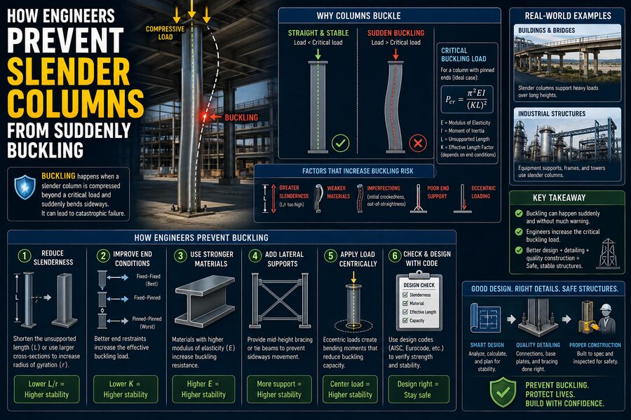

Slender columns are common in buildings, bridges, industrial structures, towers, warehouses, and many other engineering systems. They may look simple—just long vertical members carrying loads—but their structural behavior can be surprisingly complex. A short, thick column usually fails when the material itself becomes overstressed. A long, slender column, however, can fail in a completely different way: buckling. ⚠️
Buckling is especially dangerous because it can happen suddenly. A column may appear perfectly stable while carrying an increasing compressive load, then abruptly bend sideways once a critical load is reached. Engineers therefore do much more than simply check whether the steel, concrete, timber, or other material is strong enough. They carefully evaluate the column’s geometry, support conditions, stiffness, imperfections, and surrounding structural system.
Understanding how engineers prevent buckling reveals an important principle of structural design: strength alone does not guarantee stability.
🧱 What Is Column Buckling?
A column primarily carries compression, meaning forces push inward along its length. When the column is relatively short, increasing compression mainly increases stress inside the material.
A slender column behaves differently.
Even if the load is theoretically centered, tiny imperfections are always present. A real column might be slightly curved, its material may not be perfectly uniform, or the load may be applied a few millimeters away from the ideal centerline.
As the compressive force increases, these small imperfections can cause the column to deflect sideways. The sideways movement creates additional bending moments, which cause even greater deflection. Eventually, the column can become unstable and suddenly bow outward. 📐
This instability is called buckling.
The important point is that buckling can occur even when the average compressive stress is well below the material’s crushing or yielding strength.
📏 Why Slenderness Matters
One of the first things engineers examine is a column’s slenderness ratio.
A simplified expression is:
Slenderness Ratio = Effective Length ÷ Radius of Gyration
The effective length depends on how the column is restrained at its ends, while the radius of gyration describes how the cross-sectional material is distributed around its centroid.
A larger slenderness ratio generally means a greater risk of buckling.
Imagine two steel members made from the same material and carrying the same compressive force. One is short and thick, while the other is extremely tall and narrow. The short member is much less likely to buckle because its geometry provides substantially greater stability.
This is why engineers do not select columns based on material strength alone. Their length and cross-sectional geometry are equally important.
🧮 Euler’s Buckling Equation
One of the foundations of column stability analysis is Euler’s critical buckling equation, developed by mathematician Leonhard Euler.
For an ideal slender column, the critical load can be written as:
Pcr = π²EI / (KL)²
Where:
- Pcr = critical buckling load
- E = modulus of elasticity of the material
- I = second moment of area of the cross-section
- L = actual column length
- K = effective-length factor determined by end restraints
The equation immediately reveals several important engineering strategies.
Increasing E means using a stiffer material. Increasing I means arranging material farther from the column’s central axis. Reducing L or the effective length dramatically raises the buckling resistance.
Notice that the length term is squared. 📈
That means column length has a very large effect on stability. If the effective length doubles, the theoretical Euler buckling capacity becomes only one-quarter as large, assuming everything else remains unchanged.
🏢 1. Engineers Increase the Column’s Cross-Section
One straightforward method of improving buckling resistance is increasing the size of the column.
However, engineers are interested not only in the total amount of material but also in where that material is located.
Buckling resistance depends strongly on the second moment of area, I. Moving material farther from the centroid can significantly increase bending stiffness without necessarily increasing weight proportionally.
This explains why steel columns often use shapes such as:
- I-sections
- H-sections
- Hollow structural sections
- Circular tubes
- Box sections
A hollow tube, for example, can be highly efficient because much of its material is positioned away from the center, where it provides greater resistance against bending and buckling. 🔩
🔗 2. Engineers Reduce the Effective Length
Because buckling capacity varies inversely with the square of effective length, reducing that length can be extremely powerful.
Engineers commonly add lateral bracing to prevent the column from moving sideways at intermediate locations.
Consider a tall column that would otherwise be unsupported over its full height. If a brace is installed halfway up, the member may effectively behave more like two shorter column segments.
This can dramatically improve stability.
Bracing can come from:
- Beams
- Cross-bracing
- Floor systems
- Diaphragms
- Shear walls
- Trusses
- Structural frames
In real buildings, columns rarely act completely alone. Engineers design the surrounding structure so that different members support and stabilize one another. 🏗️
🔒 3. Engineers Control Column End Conditions
The way a column is connected at its ends has a major effect on its tendency to buckle.
A column with ends that can freely rotate behaves differently from one whose ends are rigidly restrained.
Typical idealized end conditions include:
Pinned–Pinned: Both ends can rotate.
Fixed–Fixed: Both ends resist rotation.
Fixed–Pinned: One end is restrained while the other can rotate.
Fixed–Free: One end is fixed while the other is completely free, similar to a flagpole.
These conditions are represented through the effective-length factor K.
A fixed-fixed column can generally resist more buckling load than a comparable pinned-pinned column because the stronger rotational restraints reduce its effective buckling length.
For engineers, connection design is therefore not merely about keeping structural members attached. Connections can directly influence the stability of the entire system. 🔧
📐 4. Engineers Design Against Buckling About the Weak Axis
Many column cross-sections are much stiffer in one direction than another.
An I-shaped steel section, for instance, typically has a strong axis and a weak axis. The column naturally tends to buckle in the direction where its flexural stiffness is lowest.
Engineers therefore calculate buckling resistance about multiple axes rather than checking only one direction.
If the weak-axis resistance is inadequate, engineers may:
- Select a different section
- Increase the section dimensions
- Add lateral bracing
- Rotate the column orientation
- Use a box or tubular section
- Reduce the unsupported length
This prevents a situation where a column appears strong in one direction but remains vulnerable in another. 🧭
⚙️ 5. Engineers Account for Real-World Imperfections
Euler’s theoretical column assumes something that never truly exists: a perfectly straight column made from perfectly uniform material with a perfectly centered load.
Real structures are imperfect.
Potential imperfections include:
- Initial crookedness
- Fabrication tolerances
- Residual stresses from welding or rolling
- Slightly eccentric loads
- Misaligned connections
- Uneven material properties
- Construction tolerances
Engineers account for these effects through modern structural design codes, safety factors, resistance factors, and advanced analytical techniques.
Rather than assuming a column remains perfectly straight until the critical load, engineers recognize that small deflections may exist from the beginning.
This makes real-world designs considerably safer than calculations based solely on idealized theory. 🛡️
🔄 6. Engineers Consider the P-Delta Effect
One of the most important concepts in slender-column design is the P-Delta effect.
Suppose a compressive force P acts through a column that has already moved sideways by a distance Δ.
The axial load then creates an additional bending moment approximately equal to:
Additional Moment = P × Δ
That extra moment produces more bending, which can increase the lateral displacement even further. The larger displacement then creates another increase in bending moment.
This feedback effect can significantly amplify structural forces.
Modern engineering analysis often includes second-order effects, meaning calculations account for the deformed shape of the structure rather than assuming that geometry remains unchanged while loads are applied.
For highly slender members and flexible frames, second-order analysis can be essential. 📊
🧩 7. Engineers Use Braced Structural Systems
Preventing column buckling is often a system-level problem rather than an individual-member problem.
Buildings can use structural systems such as:
- Shear walls
- Reinforced-concrete cores
- Diagonal steel bracing
- Moment-resisting frames
- Outrigger systems in tall buildings
These components limit sideways movement and reduce the effective unsupported length or destabilizing displacement of columns.
For example, the central concrete core of a skyscraper does much more than house elevators and stairwells. It can also provide substantial lateral stiffness against wind and earthquake forces, helping stabilize surrounding columns. 🌆
🏭 8. Engineers Choose Appropriate Materials
Material stiffness also affects buckling behavior.
Euler’s equation contains the modulus of elasticity E, which measures a material’s resistance to elastic deformation.
Steel is widely used for slender structural members partly because it provides high strength and stiffness with relatively compact cross-sections.
Concrete columns can also achieve excellent stability, especially when their dimensions are sufficiently large and reinforcement is properly designed.
Timber columns require similar stability checks but have material-specific considerations related to grain direction, moisture, imperfections, and long-term loading.
The best material depends on structural requirements, cost, fire resistance, durability, architecture, and construction method. 🧱
🏗️ 9. Engineers Prevent Local Buckling Too
A column does not always buckle as one entire member.
Thin parts of its cross-section can sometimes buckle locally.
For example, the flange or web of a thin-walled steel section might deform before the whole column experiences global buckling.
Engineers therefore check both:
Global buckling — instability involving the overall length of the member.
Local buckling — instability affecting individual plates or walls within the cross-section.
To reduce local buckling risk, designers may increase plate thicknesses, add stiffeners, change section geometry, or choose more compact structural sections.
This distinction becomes especially important in lightweight structures where engineers seek to minimize material while maintaining stability. ⚖️
🧪 10. Computer Modeling Helps Engineers Predict Instability
Modern engineering software allows structural engineers to analyze complicated columns and building frames far beyond the limitations of simple hand calculations.
Finite element analysis and structural modeling programs can simulate:
- Member imperfections
- Material yielding
- Second-order effects
- Complex connections
- Nonlinear behavior
- Multiple load combinations
- Three-dimensional buckling modes
However, software does not eliminate the need for engineering judgment.
Engineers still need to understand what the model represents, determine realistic boundary conditions, select appropriate imperfections, interpret results, and recognize potentially unrealistic outputs.
Computer analysis is most effective when combined with a strong understanding of structural mechanics. 💻
🛡️ 11. Building Codes Provide Additional Safety
Structural engineers do not normally design a column so that its expected load sits directly below its theoretical buckling limit.
Building codes and structural standards include numerous safety provisions.
Depending on the design method and material, engineers consider factors associated with:
- Uncertainty in loads
- Material variability
- Geometric imperfections
- Construction tolerances
- Buckling behavior
- Load combinations
- Resistance uncertainty
Standards such as those developed for steel, concrete, timber, and other materials contain equations based on theoretical research, laboratory testing, and decades of engineering experience.
This provides a safety margin between ordinary operating conditions and structural failure. ✅
🌬️ 12. Engineers Consider Loads Beyond Simple Gravity
Columns rarely experience perfectly centered compression.
Real buildings are exposed to wind, earthquakes, equipment vibration, temperature changes, uneven floor loading, construction loads, and accidental eccentricities.
Wind may cause a tall building to sway. Earthquake motion can repeatedly reverse forces in columns. A beam framing into one side of a column may introduce additional bending.
Engineers therefore often design columns for combined axial compression and bending, not compression alone.
These interactions are especially important for slender columns because even moderate bending can amplify instability.
🚨 Why Buckling Can Be So Dangerous
Buckling is a particularly important failure mode because instability can develop rapidly.
Unlike some forms of material failure that may be preceded by obvious cracking or gradual deformation, an unstable slender member can lose much of its load-carrying capacity after relatively small additional changes in load or displacement.
That is why engineers aim to keep structures well within stable operating ranges rather than relying on a column’s theoretical maximum capacity.
Redundancy, inspection, quality control, proper connections, and conservative code-based design all contribute to structural safety.
🌉 A Simple Way to Visualize Column Buckling
Imagine pressing downward on a short drinking straw. It may support a reasonable amount of force before deforming significantly.
Now imagine using a much longer straw of exactly the same diameter and material. Even a relatively small downward force can cause it to bow sideways.
Nothing about the material itself necessarily became weaker. The geometry changed, causing the structure to become less stable.
Structural columns follow the same fundamental principle, although real engineering calculations are far more sophisticated.
🎯 Final Takeaway
Engineers prevent slender columns from suddenly buckling by combining geometry, stiffness, restraint, bracing, accurate analysis, material selection, strong connections, and safety-focused design codes.
They increase cross-sectional stiffness, reduce unsupported lengths, account for weak-axis behavior, control end conditions, include imperfections, evaluate P-Delta effects, prevent local buckling, and analyze how columns interact with the surrounding structure.
The central lesson is simple but powerful: a structural member can have plenty of material strength and still fail because it loses stability.
That is why structural engineers ask more than, “Is this column strong enough?” They also ask, “Will this column remain stable under every realistic combination of loads?” 🏗️🔬
By answering both questions, engineers turn slender structural members into reliable components capable of safely supporting buildings, bridges, towers, and infrastructure for decades.