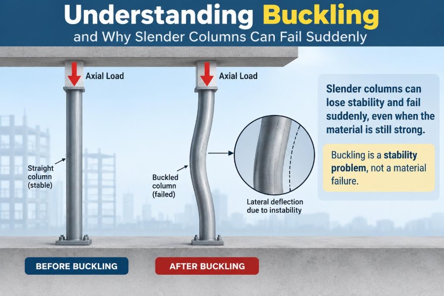

A slender steel post in a warehouse, a bridge compression member, or the thin leg of a table can appear perfectly sound while carrying load. Then, with little visible warning, it bends sideways. The material may not be crushed, torn, or even close to its usual compressive strength.
That unexpected sideways movement is a familiar structural problem called buckling. It explains why a long member can fail at a load that a shorter member of the same material and cross-section would carry comfortably.
For designers, buckling is not a niche calculation reserved for unusual structures. It influences columns, bracing, truss members, piles, walls, thin plates, shell roofs, and many components inside machines and buildings.
Understanding the mechanism changes the question from “Is there enough material?” to “Can this shape remain stable under compression?” That distinction is at the center of safe, efficient structural design.
🧭 Buckling Is a Stability Failure
Buckling occurs when a structural member under compression becomes unstable and develops a sideways deformation. Instead of continuing to shorten along its original straight line, it adopts a bent shape.
This is fundamentally different from simple crushing. Crushing is governed mainly by stress exceeding the material’s compressive capacity; buckling is governed by the interaction of load, geometry, stiffness, support conditions, and imperfections.
A member can buckle while stresses in much of its cross-section are still below the yield strength of steel or the crushing strength of concrete. Once lateral deflection begins, the internal force pattern changes rapidly.
📦 A Simple Ruler Analogy
Stand a plastic ruler upright on a desk and press down gently. A short portion of the ruler can take a noticeable force, but a long exposed length suddenly bows sideways under much less force.
The ruler has not changed material. Its vulnerability changed because its unsupported length increased. A column behaves in much the same way: length matters greatly when compression is present.
The analogy is useful, although real structures add complications such as imperfect connections, eccentric loading, residual stress, wind, and interaction with other members.
🧱 What Counts as a Column?
A column is commonly described as a member that primarily carries axial compression. In practice, many members have this role even if they are not vertical.
- A vertical building column transfers floor loads downward.
- A top chord in a truss may be in compression.
- A diagonal brace can alternate between tension and compression under lateral loading.
- A pile may carry compression from a foundation into soil.
Any sufficiently slender compression member deserves a buckling check. Orientation does not remove the stability problem.
📏 Slenderness Explains the Risk
Slenderness expresses how long a member is relative to its lateral stiffness. A long, narrow member is more slender than a short, stocky one.
Engineers commonly relate effective length to the member’s radius of gyration, a cross-sectional property that reflects how material is distributed away from the centroid. A larger radius of gyration means greater resistance to bending about that axis.
As slenderness rises, buckling becomes more likely to control design. As slenderness falls, material yielding or crushing becomes increasingly relevant.
🪵 Why Length Has Such a Strong Effect
A column’s critical elastic buckling load changes with the inverse square of its effective length. In plain terms, doubling effective length can reduce the ideal elastic buckling load to one quarter.
That relationship is why intermediate bracing can be extraordinarily valuable. Reducing the unbraced length is often more efficient than simply making every compression member much heavier.
The same principle also explains why a temporary construction-stage arrangement can be unsafe even when the completed structure is stable: the final bracing may not yet be active.
🔩 Stiffness Matters More Than Material Amount Alone
Adding material does not always improve buckling resistance equally. Where that material is placed is crucial.
A tube, wide-flange section, or built-up section can have far more bending stiffness than a solid-looking compact bar of similar area because more material lies farther from the center. This improves the section’s second moment of area, often called moment of inertia.
For a column, the relevant stiffness is its bending stiffness, represented by EI: elastic modulus E multiplied by second moment of area I. Both the material and the cross-sectional shape matter.
↔️ Every Column Has a Weak Axis
Most sections do not resist bending equally in every direction. A wide-flange steel shape, rectangular tube, timber member, or built-up section generally has a strong axis and a weak axis.
Unless restrained, the member tends to buckle about the axis with lower bending stiffness. This is the weak-axis buckling condition.
Designers therefore check both principal axes. A column that looks substantial from one viewpoint may be surprisingly flexible from another.
🧮 Euler’s Ideal Column Model
Leonhard Euler developed the classical elastic buckling model for an ideal, perfectly straight, centrally loaded, elastic column. Its critical load is commonly written as Pcr = π²EI/(KL)².
In this expression, L is actual length and K is an effective-length factor representing end restraint. The equation captures the essential trends: greater stiffness raises capacity, while greater effective length sharply reduces it.
Euler buckling is most applicable to very slender members that remain elastic up to instability. It is a foundation for understanding, not a complete substitute for modern design provisions.
🔗 End Conditions Change the Effective Length
Column ends are not all alike. A member that can rotate freely at its ends behaves differently from one held in a stiff frame connection.
| Idealized end condition | Relative buckling behavior | Design implication |
|---|---|---|
| Pinned-pinned | Baseline half-sine buckled shape | Effective length is approximately actual length |
| Fixed-fixed | Rotation restrained at both ends | Greater ideal resistance; effective length is shorter |
| Fixed-pinned | Partial rotational restraint | Intermediate behavior |
| Fixed-free | One end acts as a cantilever tip | Much lower resistance; effective length is much longer |
These are ideal cases. Actual restraint depends on connection stiffness, adjoining beams, bracing systems, foundations, and overall frame movement.
🏢 Sidesway Can Make Columns More Vulnerable
A column in a braced frame may have its ends prevented from translating sideways. In an unbraced or sway frame, an entire storey can drift laterally under wind, seismic effects, or gravity-load-induced instability.
Frame sidesway increases column moments and can increase effective length. The behavior is a system problem, not merely a property of one isolated column.
This is why assigning an optimistic end condition without evaluating the surrounding structure is risky. A connection that looks rigid may not provide enough restraint when the whole frame deforms.
🎯 Perfect Axial Load Is Rare
Textbook diagrams often show a load applied exactly through the centroid of a column. Real loads are commonly offset by small amounts because of fabrication tolerance, connection geometry, beam reactions, settlement, or construction variation.
This offset is called eccentricity. It creates bending moment in addition to compression, so one side of the column experiences higher stress than the other.
Even a small eccentricity can become significant in a slender member because lateral deflection enlarges the moment. Design methods account for this rather than assuming perfectly concentric loading.
📈 The P-Delta Effect Creates a Feedback Loop
When a compressive force P acts through a laterally displaced column, the displacement Δ creates an additional moment, approximately PΔ. This is known as the P-Delta effect.
The extra moment causes more bending, which can cause more displacement, which produces still more moment. Near instability, this feedback can greatly amplify deformation.
Second-order analysis is used when these effects are meaningful. It is especially relevant for slender columns, flexible frames, tall structures, and members carrying substantial compression.
🌊 Initial Crookedness Starts the Process
No fabricated column is perfectly straight. Members have small initial curvature, and erected frames have alignment tolerances.
Under compression, an initially crooked member immediately develops bending. The familiar notion of a perfectly straight column remaining straight until one exact critical load is therefore an idealization.
Practical design standards incorporate imperfection effects through column curves, notional loads, direct analysis approaches, or other prescribed methods. These approaches recognize real behavior without requiring every tiny deviation to be measured individually.
🔥 Residual Stress Has a Quiet Influence
Steel sections can retain internal stresses after rolling, welding, cooling, cutting, or fabrication. These residual stresses exist even when no external load is applied.
As a compression member is loaded, some fibers may reach yield earlier than a simple uniform-stress model would suggest. This reduces effective stiffness and can lower practical column strength below the ideal Euler value.
Residual stress does not mean a member is defective. It is a normal behavior considered by established steel design methods.
🧱 Short, Intermediate, and Long Columns Behave Differently
Column behavior is often understood through three broad ranges. The boundaries depend on material, section, and design method, so they should not be treated as universal fixed categories.
Short columns
Short, stocky columns are comparatively resistant to global bending. Their capacity is more likely governed by yielding in steel, crushing in concrete, or local bearing-related effects.
Intermediate columns
These members experience a combined influence of material nonlinearity and instability. Many practical building columns fall in this range.
Long columns
Very slender columns may buckle elastically at stresses well below material yield. Euler’s ideal model is most representative of this range.
🧩 Global Buckling Is Not the Only Buckling Mode
Global buckling is the overall sideways bowing of a member between its supports. But thin elements within a section can buckle locally before the full member bends globally.
For example, a slender plate element in a steel I-section may wrinkle under compression. A thin-walled tube may develop local folds. These are forms of local buckling.
A safe design must consider the mode that governs. Increasing a member’s overall size may not solve a thin flange or wall problem if local slenderness remains excessive.
🪜 Torsional and Flexural-Torsional Buckling
Some open or unsymmetrical sections can twist as they buckle. This is called torsional buckling when rotation is dominant, or flexural-torsional buckling when bending and twisting occur together.
Angles, tees, channels, and built-up members can be susceptible depending on their geometry and restraint. The location of the shear center, which may not coincide with the centroid, becomes relevant.
These modes are a reminder that “sideways bending” is a useful first picture, not the complete story for every section.
🧷 Bracing Changes the Structural Question
A lateral brace restrains movement at a point along a compression member. If it is adequately stiff and strong, it can divide a long unbraced length into shorter segments.
However, a brace is useful only if it has a complete load path. It must resist the force generated as the member tries to bow, and that force must travel through connections into a stable bracing system or diaphragm.
A nominal brace attached to a flexible member, weak connection, or unanchored system may not provide the assumed restraint.
🛠️ Bracing Must Restrain the Right Direction
Because columns can buckle about different axes, bracing must be oriented to restrain the relevant mode. A restraint effective in one direction may leave weak-axis movement largely uncontrolled.
For beams, compression flanges may need lateral restraint to prevent lateral-torsional buckling. For truss compression chords, out-of-plane bracing is often as important as in-plane geometry.
Connection detailing matters too. A brace that restrains translation but permits harmful rotation may not deliver the assumed level of stability.
🏗️ Construction Stages Are Often the Critical Stage
The completed structure may be stable because floors, roof diaphragms, cladding, cross-bracing, and permanent connections work together. During erection, some of those elements may be absent or only partially engaged.
Temporary loads from workers, equipment, stored materials, or wind can act on a frame whose intended lateral system is incomplete. Temporary bracing and an erection sequence are therefore engineering controls, not administrative details.
Design assumptions should be checked against how the structure will actually be assembled and supported at each stage.
🏠 Concrete Columns Need Slenderness Checks Too
Concrete is strong in compression, but reinforced concrete columns can still be slender enough for instability and second-order moments to matter. Cracking, creep, shrinkage, reinforcement layout, and sustained load can affect stiffness.
Design procedures use effective stiffness rather than assuming the gross, uncracked concrete section supplies full long-term rigidity. End restraint and frame sway remain important.
Concrete confinement and reinforcement improve behavior, but they do not eliminate the need to evaluate slenderness.
🌲 Timber Adds Material-Specific Considerations
Timber compression members are also vulnerable to buckling, particularly when long and lightly braced. Wood is orthotropic: its properties differ along and across the grain.
Moisture condition, knots, grain deviation, connection detailing, and long-term load effects can influence capacity. Engineered wood members may have different behavior from sawn timber, but both require stability checks.
Careful bearing details help keep load paths aligned and reduce unintended eccentricity at supports.
🔍 A Hypothetical Design Comparison
Imagine two steel columns of the same section carrying the same axial load. One is part of a single-storey, well-braced frame with reliable restraint at floor and roof levels. The other spans a tall open space with no intermediate lateral support.
Although their material and cross-section are identical, the taller unbraced column has a much larger slenderness ratio. It will require a more careful stability check and may need a larger section, a different shape, added bracing, or a revised framing arrangement.
This is hypothetical, but it reflects a common design lesson: capacity is a property of the member within its structural system, not the member alone.
⚠️ Common Mistake: Checking Stress but Ignoring Stability
A basic axial stress calculation divides force by area. It is useful, but it does not reveal whether the member can remain straight under load.
A slender column can show a modest average compressive stress and still buckle. Conversely, a compact column may be controlled by material strength rather than global instability.
Good design checks both resistance to stress-related failure and resistance to stability-related failure, using the applicable material and structural design rules.
⚠️ Common Mistake: Assuming Fully Fixed Connections
Calling a connection “fixed” is not enough. Rotational restraint depends on connection geometry, bolts or welds, supporting members, panel-zone behavior, foundation flexibility, and the force level.
Overestimating fixity can make the assumed effective length too short and overstate column capacity. Conservative idealization may be appropriate when restraint cannot be demonstrated.
Conversely, providing and verifying genuine restraint can be an efficient way to improve system performance.
⚠️ Common Mistake: Treating Bracing as Secondary
Bracing is sometimes viewed as a minor accessory to the main structure. In a stability system, it is part of the main structure.
Its members, connections, collectors, diaphragms, and supports must all be designed for their roles. Removing or relocating a brace for architectural, mechanical, or construction reasons can alter the behavior of multiple compression members.
Coordination is especially valuable early in a project, when a revised bay layout or hidden brace line is easier to accommodate.
📐 What Engineers Check in Practice
A typical compression-member design process combines calculation, modeling, and detailing review. The exact workflow depends on the project, material, and governing code.
- Identify factored load combinations and load paths.
- Determine unbraced lengths and likely buckling axes or modes.
- Assess end restraint and whether the frame can sway.
- Check global, local, torsional, and interaction effects where applicable.
- Include second-order effects when required by the structural behavior.
- Design braces and connections as real force-resisting components.
- Review construction-stage stability and fabrication assumptions.
Computer analysis can support these tasks, but it does not replace judgment about boundary conditions, imperfections, and the realism of the model.
💻 What a Structural Model Can and Cannot Tell You
Analysis software can calculate forces, deflections, mode shapes, and stability-related quantities efficiently. It is particularly useful for frames where member behavior and global sway interact.
But a model only represents the restraints, stiffnesses, releases, load positions, and imperfections entered into it. An unintended release or omitted brace can change results dramatically; an unrealistic fixed support can create false confidence.
Hand checks, visual review of deformed shapes, and comparison with simple expected behavior remain valuable quality-control tools.
🧰 Practical Ways to Improve Buckling Resistance
The most effective solution depends on why a member is vulnerable. Common strategies include:
- Reduce unbraced length with properly designed lateral bracing.
- Choose a section with greater stiffness about the governing axis.
- Use closed or better-balanced shapes where torsional behavior matters.
- Improve connection and frame restraint when it can be reliably achieved.
- Reduce load eccentricity through aligned detailing and bearing.
- Use built-up members or additional material strategically, while checking local buckling.
- Revise the structural layout so compression is shared by more stable load paths.
The best option is often architectural and structural coordination rather than simply selecting a heavier member.
🧠 Buckling Is a System-Level Design Challenge
It is tempting to treat each column as an isolated vertical bar. Real stability depends on beams, slabs, diaphragms, foundations, bracing, connections, neighboring columns, and load sequence.
For example, a floor diaphragm may restrain column movement only if it is connected and capable of transferring the needed forces. A foundation may provide less rotational restraint than assumed if soil and base-plate behavior are flexible.
Thinking in systems prevents a common error: assigning a restraint in calculation that does not exist as a physical load path.
🧪 Inspection Clues and Field Awareness
Visible bowing, unexpected frame drift, distortion of thin plates, loose bracing connections, or construction changes near compression members deserve engineering attention. They do not automatically prove imminent failure, but they can indicate that assumptions have changed.
Do not attempt to straighten, unload, modify, or brace a visibly distressed structural member without a qualified assessment. Altering load paths can introduce new hazards.
For existing structures, evaluation may require measurements, material information, connection inspection, review of alterations, and analysis by an appropriately qualified engineer.
📚 Codes Turn Theory into Design Resistance
Modern structural design standards do not ask designers to rely on Euler’s formula alone. They provide member-strength equations and rules calibrated for real imperfections, residual stress, inelastic behavior, local instability, load combinations, and safety formats.
The applicable standard depends on location, material, building type, and project requirements. Engineers must use the governing edition and consider project-specific conditions rather than transferring a formula blindly from a textbook or another jurisdiction.
Code compliance is a structured minimum framework; sound engineering also requires correct modeling, constructible detailing, inspection, and responsible changes during construction.
🎓 The Core Principle to Remember
Buckling teaches a powerful structural lesson: compression capacity is not determined by area and material strength alone. A member must also have enough stiffness and restraint to maintain a stable shape.
Longer unsupported length, lower weak-axis stiffness, flexible end conditions, eccentricity, initial curvature, and sidesway all make instability more influential. Bracing, intelligent section selection, realistic connections, and system-level thinking can control those risks.
When assessing a compression member, ask not only “How much load can it carry?” but also “What stops it from moving into a buckled shape?” That question leads directly to better structural decisions.
Slender columns can fail suddenly because stability can be lost before the material itself appears fully used; sound design makes the load path, restraint, and deformation behavior work together. 🏗️📐🔩