
Picture standing in a modern hospital during an earthquake. The structure may remain standing, but that is only part of the outcome that matters. Patients, medical equipment, ceilings, pipes, elevators, and emergency operations all need to remain usable when the shaking stops.
For much of engineering history, the central goal was straightforward: make a building strong enough to resist earthquake forces. That approach saved lives and remains fundamental. But it can also send large forces into columns, walls, connections, and contents.
Earthquake engineering has gradually shifted from asking only, “Will the building collapse?” to asking, “How much will it move, what will be damaged, and can it function afterward?” That shift led to sophisticated protection systems that manage motion rather than merely fighting it.
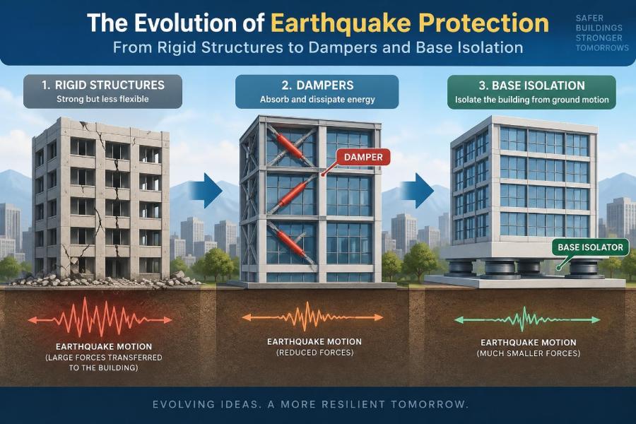
Rigid frames, ductile detailing, dampers, and base isolation are not competing eras in a simple story of old versus new. They are tools developed to solve different parts of the same problem: protecting people and the built environment from unpredictable ground motion.
🌍 Earthquakes Move the Ground, Not Just Buildings
An earthquake begins with rapid movement along a fault, releasing energy that travels through the ground as seismic waves. A building’s foundation moves with that ground, while the mass above resists acceleration because of inertia.
This mismatch produces deformation. Floors shift relative to one another, columns bend, walls crack, and connections rotate. The structural challenge is not that the earth “pushes” a building from one side; it is that the building’s own mass develops inertia forces as its support moves beneath it.
A useful analogy is a passenger in a bus that suddenly turns. The bus moves first, while the passenger’s body tends to continue in its prior direction. In a building, the floors are the passengers and the structural system must control their relative movement.
⚖️ The Basic Equation Behind Seismic Force
A simplified starting point is Newton’s relationship: force equals mass times acceleration. Heavier buildings can develop larger inertia forces when subjected to the same acceleration, although the actual response also depends heavily on stiffness, shape, period, damping, soil conditions, and the earthquake’s frequency content.
Engineers therefore do not design by multiplying a building’s mass by one universal earthquake acceleration. Codes use procedures that represent likely hazard, structural behavior, ductility, importance, and other factors. Advanced projects may use response-history analysis with recorded or simulated ground motions.
Seismic design is fundamentally a dynamic problem. The timing and frequency of motion matter, not only its peak intensity.
📏 Period: A Building’s Natural Rhythm
Every structure has one or more natural vibration periods: characteristic times required to sway back and forth. A short, stiff building usually has a shorter period than a tall, flexible one.
If earthquake motion contains strong energy near a structure’s natural period, the motion can be amplified. This is resonance—not a guarantee of dramatic failure, but a mechanism that can increase response when the timing of ground motion and structural vibration align.
Protection strategies often work by changing this relationship. Base isolation lengthens the effective period. Dampers increase energy dissipation. Stiffening systems alter both force paths and vibration characteristics.
🧱 The Early Preference for Strength and Stiffness
Early earthquake-resistant construction often emphasized thick walls, heavy materials, strong frames, and a direct load path to the ground. A stiff structure limits drift, which can protect brittle partitions, cladding, and other nonstructural components during modest shaking.
However, stiffness has a trade-off. When a stiff building moves with the ground, it may attract substantial acceleration and internal force. Making members larger is sometimes appropriate, but strength alone does not eliminate the energy that an earthquake introduces.
Rigid construction also becomes problematic when it is irregular, poorly connected, or unable to deform without sudden loss of capacity. “Strong” is not the same as “earthquake-resistant.”
🔩 Why Connections Became a Central Concern
Earthquakes expose weak links. A wall may be robust while its roof connection is inadequate; a beam may be strong while the joint that joins it to a column is vulnerable. Loads must travel continuously from floors and roofs through the lateral system and into the foundation.
This is why seismic design pays close attention to diaphragms, collectors, anchors, reinforcement development, welds, bolts, and detailing at joints. A load path is only as reliable as its discontinuities.
Connection failures can also be brittle: they may occur with little warning and limited deformation. Modern detailing seeks to avoid this by providing reliable, inspectable, and appropriately ductile connections.
🧠 Ductility Changed the Design Philosophy
Ductility is the ability to deform significantly while retaining useful strength. Rather than demanding that every member remain perfectly elastic during a rare severe earthquake, engineers can design selected components to yield in controlled ways.
A paper clip illustrates the distinction. It first bends elastically and springs back; with further bending, it plastically deforms. Structural yielding is more complex and must be carefully controlled, but the general concept is similar: deformation can absorb energy.
Ductility does not mean accepting random damage. It means choosing locations and mechanisms where inelastic behavior can occur without a sudden collapse mechanism.
🪢 Capacity Design: Choosing What Yields First
Capacity design establishes a hierarchy of strength. Components intended to remain essentially elastic are designed with sufficient capacity, while designated ductile elements are detailed to yield and dissipate energy.
For example, a moment frame may be proportioned and detailed so that beam ends yield before columns form a dangerous story mechanism. In a braced frame, specific brace or connection behavior may be intended to govern, depending on the system.
This approach recognizes that severe shaking can exceed practical elastic design levels. The objective is to guide damage toward predictable, repairable, and non-catastrophic behavior.
🏢 Moment Frames and Controlled Sway
In a moment-resisting frame, beams and columns are connected so that bending moments can transfer through the joints. The frame resists lateral loads by flexing, allowing a building to sway while maintaining a stable vertical load path.
Moment frames can provide architectural openness because they do not necessarily require large solid walls in every direction. Their flexibility, however, can lead to larger interstory drift than a wall-dominated structure of similar height.
Reliable performance depends heavily on joint detailing, confinement reinforcement in concrete, weld and connection quality in steel, and careful consideration of panel-zone and connection demands.
🧱 Shear Walls and Braced Frames
Shear walls resist lateral forces primarily through in-plane shear and bending. Concrete walls, reinforced masonry walls, and properly designed wood structural panel walls can provide efficient lateral resistance and limit drift.
Braced frames use diagonal members to form triangulated load paths. They can be highly efficient because axial action in braces often carries lateral load more directly than bending action in an unbraced frame.
Neither approach is automatically superior. Walls can complicate openings and foundations, while braces affect layouts and may buckle or yield under cyclic loading. The best system depends on the building’s height, use, materials, architecture, and seismic demands.
📉 Drift Is Often the Damage Driver
Interstory drift is the relative lateral displacement between two adjacent floors, often expressed as a ratio of story height. It is one of the most useful indicators of likely damage to partitions, façades, glazing, stairs, elevators, piping, and other building components.
A building can avoid collapse yet experience costly downtime if excessive drift damages systems needed for operation. Conversely, a very stiff system may control drift but transfer high acceleration to equipment and contents.
Seismic design therefore balances competing demands: drift control, acceleration control, strength, ductility, construction practicality, and cost. There is no single response measure that tells the complete story.
🧩 The Problem of Brittle Materials and Details
Brittle behavior provides limited warning and little ability to absorb energy through deformation. Unreinforced masonry, poorly confined concrete, weak weld details, and certain connection arrangements can be especially vulnerable when subjected to repeated reversing cycles.
In older construction, heavy masonry walls may crack and separate if they lack adequate ties to diaphragms and out-of-plane support. Concrete elements may lose capacity if reinforcement is insufficiently anchored or confined.
Retrofitting often begins by identifying these weak details, not by adding material everywhere. Targeted anchors, collectors, wall strengthening, diaphragms, or connection upgrades can address the actual failure path.
🔄 Cyclic Loading Is Different From a Single Push
Earthquake forces reverse direction repeatedly. A brace that performs adequately under one monotonic pull may behave very differently when compressed, buckled, unloaded, and pulled again.
Repeated cycles can degrade stiffness and strength, widen cracks, damage connection components, and accumulate residual deformation. Laboratory cyclic tests and analytical models help engineers understand these effects before systems are used in practice.
This is why a simple static lateral-force check, while useful within its intended design procedure, cannot fully describe seismic performance. The history of loading matters.
🌊 Soil Can Reshape the Structural Problem
The ground beneath a building is part of the seismic system. Soft soils can amplify certain motions, prolong shaking, or cause a structure to respond differently than it would on stiff rock. Foundation flexibility can also affect the vibration characteristics of the building.
Liquefaction presents a separate concern in susceptible saturated loose soils. During intense shaking, pore-water pressure can rise and soil can temporarily lose much of its ability to support loads, leading to settlement, lateral spreading, or foundation movement.
Geotechnical investigation is therefore not an administrative formality. It informs site classification, foundation design, retaining structures, ground improvement decisions, and the feasibility of isolation systems.
🧭 Irregularity Can Concentrate Damage
Structures rarely behave as ideal rectangles. Setbacks, open ground floors, large atriums, uneven wall layouts, discontinuous columns, and asymmetric floor plans can create irregular load paths and torsional response.
Torsion occurs when the center of mass and the effective center of lateral resistance are not aligned, causing a building to twist as well as translate. One edge may then experience much larger drift than another.
A soft story is another well-known concern: a floor significantly more flexible or weaker than stories above, often created by open parking or storefront space. Regularity is not merely aesthetic; it makes seismic behavior easier to predict and control.
🛠️ Retrofitting Made Performance Goals More Practical
Many existing buildings were designed under older knowledge and codes, or were not designed for seismic resistance at all. Demolition and replacement may be unrealistic, especially for occupied, historic, or essential facilities.
Retrofit strategies range from adding walls or braces to strengthening diaphragms, jacketing columns, improving connections, reducing hazardous mass, and installing supplemental damping or isolation. The appropriate choice follows an evaluation of expected weaknesses and desired performance.
A retrofit does not need to make an older building identical to a new one. It should establish a realistic, explicitly stated objective: life safety, reduced damage, continued occupancy, or protection of critical functions.
💥 Why Simply Making Everything Stronger Has Limits
Increasing member sizes can reduce some deformations, but it can also increase seismic mass, foundation demands, connection forces, and construction disruption. In a retrofit, new stiff elements may attract force away from existing elements in unexpected ways.
Strengthening one portion of a building without checking the entire load path can shift rather than solve the problem. For example, a stronger wall requires capable diaphragm collectors and foundations to deliver and resist its forces.
This limitation helped drive interest in systems that dissipate energy or decouple the superstructure from ground motion, instead of relying only on added stiffness and strength.
🧯 What Structural Dampers Do
Dampers are devices installed within a structural system to absorb or dissipate a portion of earthquake energy. They act somewhat like shock absorbers in a vehicle, although their mechanisms and design demands vary considerably.
By removing energy from vibration, dampers can reduce displacement, acceleration, or both, depending on the device and structural arrangement. They do not make a building motionless, and they must be integrated with a reliable primary lateral-force-resisting system.
Supplemental damping is particularly useful where engineers need to improve performance without greatly increasing member sizes or where limiting response protects valuable contents and nonstructural systems.
🌀 Viscous Dampers and Velocity-Dependent Resistance
Viscous dampers typically force fluid through or around internal components as the device strokes. Their resistance is related to velocity, meaning they generally provide more resistance when the building moves faster.
These devices can be placed in braces, chevrons, or other configurations that translate story drift into damper movement. Proper geometry matters: a device that experiences little stroke cannot provide its intended contribution.
Viscous dampers are often attractive because they can add damping without substantially increasing the structure’s static stiffness. Yet seals, connections, temperature effects, inspection access, and long-term maintenance requirements must be addressed in the project design.
🔧 Friction, Metallic, and Viscoelastic Dampers
Other damper families dissipate energy through frictional sliding, yielding metal components, or deformation of viscoelastic materials. Each has a distinct force-deformation relationship, often represented by a hysteresis loop during cyclic testing.
| Damper type | Primary mechanism | Typical design consideration |
|---|---|---|
| Viscous | Fluid resistance during motion | Velocity, stroke, seals, and temperature |
| Friction | Controlled sliding at interfaces | Slip force and repeatable surface behavior |
| Metallic yielding | Stable inelastic deformation of steel | Low-cycle fatigue and replaceability |
| Viscoelastic | Shear deformation of polymeric material | Frequency and temperature sensitivity |
Selection is not a matter of choosing the device with the largest advertised force. Engineers must evaluate expected displacements, cycling, installation tolerances, inspection needs, and how the device changes the overall structural response.
🧱 Buckling-Restrained Braces as Energy Dissipaters
A conventional steel brace is strong in tension but may buckle in compression. Once buckled, its cyclic response can degrade and introduce unbalanced forces.
A buckling-restrained brace, often called a BRB, uses a steel core that yields in both tension and compression while a surrounding restraining system prevents global buckling. The result can be stable, repeatable energy dissipation when properly designed and detailed.
BRBs are not passive accessories that can simply be inserted into any frame. Their connections, collectors, foundation loads, compatibility with adjacent framing, and post-earthquake replacement strategy require careful consideration.
🚉 Base Isolation Changes the Starting Point
Base isolation places flexible and often energy-dissipating elements between the building and its foundation or substructure. Instead of forcing the entire superstructure to follow rapid ground motion closely, the isolation layer permits controlled horizontal movement.
This typically lengthens the effective vibration period and can reduce acceleration transmitted into the supported building. For equipment-sensitive or operationally critical facilities, lower floor accelerations can be as valuable as reduced structural damage.
Think of carrying a tray while walking across a vibrating platform. If a well-designed cushioning layer separates the tray from the platform, the tray may experience a smoother motion—though it still moves and needs room to do so.
🧊 Common Forms of Base Isolators
Elastomeric bearings use layers of rubber-like material bonded to steel shims. Some incorporate a lead core or other mechanism to add energy dissipation and restoring behavior. Their vertical stiffness supports gravity loads while their horizontal flexibility permits lateral movement.
Sliding systems use carefully engineered surfaces that allow controlled movement, often with a curved geometry that helps provide restoring action. Their friction characteristics influence energy dissipation and response.
Real projects may use more than one device type. The essential question is not the product category but whether the system provides adequate displacement capacity, vertical support, restoring characteristics, durability, and protection against unintended restraint.
↔️ The Isolation Moat Is Not Optional
An isolated building needs clearance to move relative to surrounding ground, retaining walls, adjacent structures, and utility connections. This protected gap is often called an isolation moat.
If the building strikes a rigid obstacle during design-level movement, the assumed isolation behavior changes abruptly. Impact can create high forces and damage both the structure and the obstacle.
Utilities must also cross the isolation plane using flexible, appropriately detailed connections. Stairs, ramps, elevators, fire protection piping, electrical systems, and architectural finishes all require coordination. Base isolation is a whole-building strategy, not a foundation-only detail.
🏥 Where Base Isolation Is Especially Valuable
Isolation is often considered for hospitals, emergency facilities, museums, data-related facilities, and buildings housing sensitive equipment or irreplaceable contents. It can also suit residential, office, educational, and civic projects where reduced damage and downtime justify the added complexity.
Its benefits are most compelling when the superstructure can remain relatively regular and when the site, seismic hazard, and performance objectives align with the system’s strengths. Very soft soil, extreme near-fault displacement demands, steep sites, or constraints on movement space may require different solutions or more specialized evaluation.
Isolation does not remove the need for robust superstructure design. The building above the isolation plane still needs to handle its own deformations, vertical loads, wind demands, and residual seismic actions.
🚧 Near-Fault Motions Require Extra Care
Sites close to active faults may experience strong velocity pulses or permanent ground displacement. These effects can impose large demands over a relatively short time and may challenge conventional assumptions about expected displacement.
For an isolated structure, large relative movement is central to the design problem. Engineers may need to examine moat clearance, isolator displacement capacity, impact protection, and the possibility that fault rupture hazards cannot be addressed by structural isolation alone.
No device is a universal remedy for site hazards. Sound seismic design starts with hazard characterization and uses systems compatible with that hazard.
📊 Comparing the Main Protection Approaches
The following comparison is deliberately broad. Actual performance depends on structural configuration, detailing, analysis method, site conditions, and workmanship.
| Approach | Main response strategy | Potential advantage | Key caution |
|---|---|---|---|
| Strength and stiffness | Resist force and limit deformation | Direct, familiar load path | Can attract high forces and accelerations |
| Ductile structural system | Deform in controlled yielding zones | Reliable life-safety behavior when detailed well | Damage and repair may still be significant |
| Supplemental damping | Dissipate vibration energy | Can reduce motion without major stiffening | Requires device-specific design and maintenance |
| Base isolation | Decouple superstructure from ground motion | Often reduces transmitted acceleration | Needs movement space and coordinated details |
🧰 Nonstructural Components Need Equal Attention
In many buildings, injury, financial loss, and downtime arise from nonstructural damage rather than collapse of the main frame. Ceiling systems, mechanical units, storage racks, façades, laboratory equipment, and piping can all create serious consequences.
Seismic restraints for these components must accommodate expected building movement while preventing falling, overturning, rupture, or collision. A highly advanced structural system cannot fully protect an unanchored server rack or a brittle pipe connection that crosses a moving joint.
For owners, this is a practical lesson: performance goals must include the systems needed to use the building after an event.
🔍 Analysis Models Must Match the Question
Equivalent lateral-force procedures can be appropriate for many regular buildings within their code limits. More complex, tall, irregular, damped, or isolated structures may require modal response spectrum analysis, nonlinear static procedures, or nonlinear response-history analysis.
More advanced analysis is not automatically more accurate. It depends on reasonable modeling assumptions, carefully selected ground motions where required, sound interpretation, and independent review appropriate to project complexity.
Models should represent the features that govern behavior: stiffness distribution, mass, diaphragm action, soil-structure interaction where relevant, nonlinear components, damper properties, isolator behavior, and realistic boundary conditions.
🧪 Testing, Quality Control, and Inspection
Seismic performance is not created only in calculation software. Material testing, special inspection, welding procedures, reinforcement placement, bolt installation, concrete consolidation, and field verification strongly influence whether a structure matches its design intent.
For damping and isolation devices, qualification and production testing may be required by applicable project criteria. Device properties, identification, storage, installation orientation, and final access for inspection should be documented.
A common risk is treating proprietary devices as black boxes. Their force, stroke, connection demands, tolerances, and long-term service conditions must be understood by the full design and construction team.
🛡️ Maintenance and Post-Earthquake Decisions
Some systems are designed to remain largely elastic, while others intentionally yield or dissipate energy through components that may need inspection or replacement after strong shaking. A post-event plan should identify what must be checked and who is authorized to make occupancy decisions.
Dampers may need evaluation for leakage, displacement, connection damage, or altered properties. Isolation bearings and sliding components need inspection for displacement, surface condition, stops, surrounding moat clearance, and utility connections.
Planning this process before an earthquake improves recovery. The goal is not to assume a building is safe because it looks undamaged, nor to assume it is unusable because it moved as designed.
⚠️ Common Misconceptions About Earthquake Protection
- “A rigid building is always safer.” Stiffness can reduce drift but may increase force and acceleration demands.
- “Dampers replace the structural frame.” Dampers supplement a designed load-resisting system; they do not excuse weak gravity or lateral load paths.
- “Base-isolated buildings do not shake.” They still move, and their isolators may undergo substantial displacement.
- “Code compliance means no damage.” Building codes generally establish minimum objectives that vary by occupancy and system, not a universal promise of immediate functionality.
- “One retrofit fixes the whole building.” Every modification must be checked within the full force path and configuration.
👷 Early Collaboration Produces Better Systems
Earthquake protection affects architecture, structure, geotechnical engineering, mechanical and electrical design, fire protection, construction sequencing, and facility operations. The earlier these disciplines coordinate, the fewer late conflicts arise.
For example, an isolation moat influences site grading and entrances; a damper brace affects room planning and façade openings; a new shear wall can interrupt mechanical distribution. These are design choices, not afterthoughts.
Students should learn to see seismic design as coordination across systems. Working professionals should bring contractors, specialty suppliers, and inspectors into the conversation early enough to resolve buildability concerns.
🎯 Performance-Based Design Looks Beyond Minimum Survival
Performance-based seismic design evaluates how a building may behave at different shaking levels against selected objectives. Rather than using only a single pass/fail idea, it can consider repair cost, downtime, residual drift, component damage, and functionality.
This does not make prediction exact. Earthquakes are variable, models carry uncertainty, and actual construction differs from idealized assumptions. But explicitly discussing desired performance helps owners make informed decisions about resilience investments.
A school, laboratory, warehouse, and emergency operations center may have very different acceptable outcomes. The right system follows the consequences of interruption as well as structural safety.
🌱 The Core Principle: Manage Motion, Not Just Force
The evolution from rigid construction toward ductile frames, dampers, and base isolation reflects a deeper understanding of earthquake behavior. Buildings cannot command the ground to stop moving, but they can be configured to respond in safer and more useful ways.
Strength provides resistance. Stiffness controls some deformation. Ductility prevents abrupt failure by allowing controlled inelastic action. Damping removes vibrational energy. Isolation reduces how directly rapid ground motion reaches the superstructure.
The most resilient design is not the one that relies on a single feature, but the one that aligns load paths, deformation capacity, energy dissipation, site conditions, nonstructural protection, and realistic performance goals.
Earthquake protection has evolved from resisting every possible movement toward understanding, directing, and reducing damaging motion. That evolution gives engineers a broader toolkit—and a clearer responsibility to select and detail each tool for the building, site, and people it serves. 🏗️ 🌍 🛡️