
Working stress method is used for the design of Reinforced concrete, Steel and Timber structures. The main assumption in the WSM is that the behaviour of structural material is restricted with in linear-elastic region and the safety of it is ensured by restricting the stresses coming on the members by working loads. Thus the allowable stresses will come in the linear portion (i.e., initial phase) of the stress-strain curve. Thus a factor of safety was introduced to the design
“Factor of safety is the ratio of strength of material to the permissible stress”
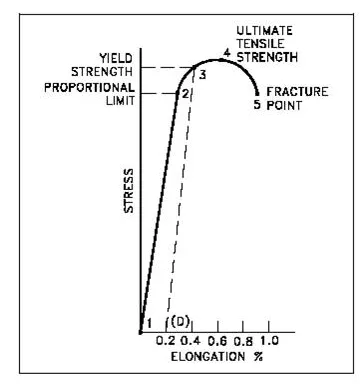
Yielding of Steel – Stress Strain Curve
When we consider the effect of creep, shrinkage, stress concentrations and others secondary effects the assumption of material behavior in the elastic range will not hold. These will lead to increase of stresses into the inelastic range. WSM cannot account for loads acting simultaneously, but has different degrees of uncertainty. It cannot account for the loads having counteracting effects, such as dead load and wind load. The above will lead to non-conservative design. Working Stress method will lead to large FOS and over-sized sections, thus reducing the design economy.
WSM is still being using in special structures such as water tanks, chimneys in India. Elastic regions holds good in serviceability checks such as crack width, deflection etc.
Ultimate Load Method
This is also known as load factor method or ultimate strength method. In this we make use of the nonlinear region of stress strain curves of steel and concrete. The safety is ensured by introducing load factor.
“Load factor is the ratio of ultimate strength to the service loads”
The ULM makes it possible to consider the effects of different loads acting simultaneously thus solving the shortcomings of WSM. As the ultimate strength of the material is considered we will get much slender sections for columns and beams compared to WSM method. But the serviceability criteria is not met because of large deflections and cracks in the sections. The fall-back in the method was that even though the nonlinear stress strain behaviour of was considered sections but the nonlinear analysis of the structural was not carried out for the load effects. Thus the stress distribution at ultimate load was just the magnification of service load by load factor following the linear elastic theory.
Limit State Method
This philosophy is an advancement over the traditional design philosophies. It considers the safety at the ultimate load and serviceability at the working load, sort of extension of the WSM and ULM.
“Limit state is the state of impending failure, beyond which a structure ceases to perform its intended function satisfactorily, in terms of either safety or serviceability.”
There are 2 types of limit states
1. Ultimate Limit State: It considers strength, overturning, fatigue, sliding etc.
2. Serviceability Limit State: It considers crack width, deflection, vibration etc.
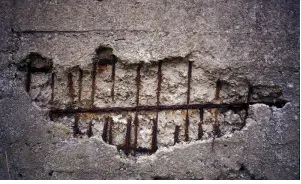
Spalling of Concrete slab due to corrosion
It uses multiple safety factors for the required safety and serviceability at the ultimate load and working load respectively by considering all limit states. These are called “partial safety factors”.
Partial safety factor for materials:
The strength of concrete in actual structure is taken as (0.67 *characteristic strength), i.e. 0.67 fck. The partial safety factor (for ultimate limit state) for concrete is 1.5 and that for steel is 1.15. The value is higher for concrete as it is expected to have more variability compared to steel. The partial safety factor (for serviceability limit state) for concrete and that for steel is taken as 1.0. This is taken as unity as we are interested in estimating the actual deflections are crack width during service loads.
Partial safety factor for loads:
Various load combinations is specified in IS 456 are
For Ultimate limit states
· UL = 1.5(DL+LL)
· UL = 1.5(DL+QL) OR 0.9DL+1.5QL
· UL = 1.2(DL+LL+QL)
The load factor of 1.2 is considered for the combination of three because the probability of the three loads reaching its peak together are less.
For serviceability limit states
· SL = 1.0 (DL+LL)
· SL = 1.0 (DL+QL)
· SL = 1.0DL+ 0.8LL+ 0.8 QL
The load factor is taken as 0.8 in the third case as the probability of wind load or earthquake load acting with the peak of live load is less. For all cases the safety factor is taken as 1.0 as we are considering the serviceability of structure here.
Where DL is dead load, LL is live load and QL is earthquake/wind load.

Comments are closed