
For the analysis of non-sway frames, the moment distribution method may be applied in the exact same way as for beams. The only difference is that there may be more than two elements attached to each node. Distribution factors can easily be calculated for such nodes as previously shown and discussed in Figure 10.4.
For sway frames, extra steps are required. A unit deformation must be applied to the degree-of-freedom associated with the sway, and the resulting force must be scaled to the force resulting from the full system restrained at that degree of freedom. Analysis of sway frames using the moment distribution method is not within the scope of this book.
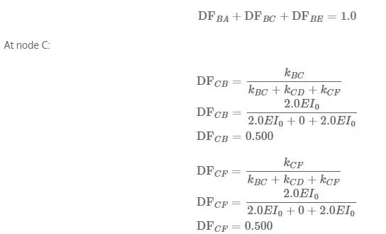
The remainder of the distribution factor are calculated based on the relative stiffness of all of the members framing into a joint (as previously shown in Figure 10.4). At node B:
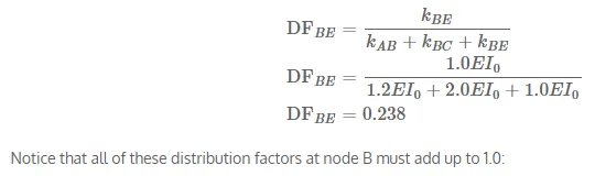
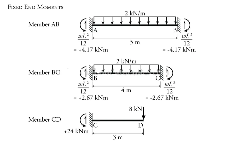
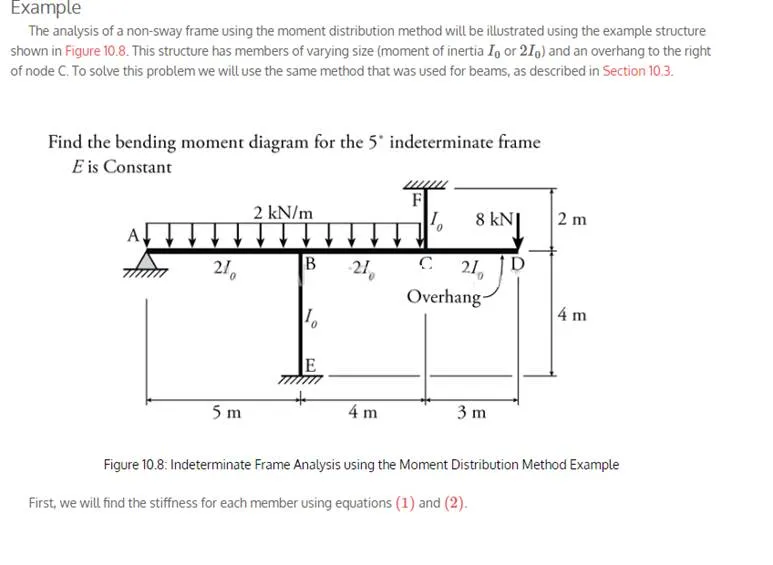
We now have all of the input parameters that are necessary to solve the moment distribution analysis.
The moment distribution analysis is shown in Table 10.2.
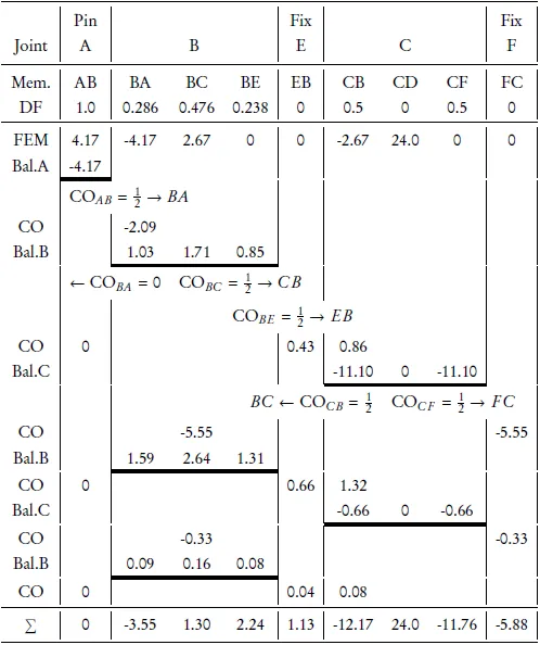
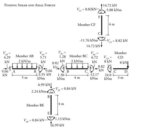
Once we have finished the iterative part of the moment distribution method analysis, we can use the end moments to calculate the shears and axial forces in each member of the frame as shown in Figure 10.10. This is the same as what was done previously in the slope deflection method analyses
Figure 10.10: Indeterminate Frame Analysis using the Moment Distribution Method Example – Finding Shear and Axial Forces
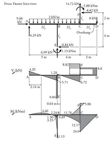
Then, knowing the shears and end moments, the shear and moment diagrams for the frame may be constructed as shown in Figure 10.11.
.
Figure 10.11: Indeterminate Frame Analysis using the Moment Distribution Method Example – Shear and Bending Moment Diagrams

Comments are closed