The slope-deflection method relies on the use of the slope-deflection equation, which relate the rotation of an element (both rotation at the ends and rigid body rotation) to the total moments at either end. The ultimate goal is to find the end moments for each member in the structure as a function of all of the DOFs associated with both ends of the member. From there, we can apply equilibrium conditions at all of the joints to solve for the unknown rotations. This is the system of equations that we will have to solve, where the equations are the equilibrium equations for each node and the unknowns are the translations and rotations of the nodes.
So, the first step is that we need an expression for the moment at each end of an arbitrary member in an indeterminate structure in terms of the rotations and translations of the nodes at either end. If there are loads between the nodes (i.e. distributed or point loads or moments along the length of the member), then we will need a way to consider the effect of those as well.


.

Figure 9.2: Deformation of a Finite Portion of an Indeterminate Structure
The arbitrary portion of an indeterminate structure shown in Figure 9.2 may also be considered to have some arbitrary external loading between the two end nodes as shown.
It is important to point out that, as shown in Figure 9.2, since the slope-deflection method will involve evaluating equilibrium of individual point moments at different nodes, then we are most interested in the absolute rotational direction of the moments, not the internal moment sign convention (see previous Section 1.6). So, we will consider all counter-clockwise moments to be positive and all clockwise moments to be negative.


.

Figure 9.3: Superposition of the Moments in a Finite Portion of a Continuous Indeterminate Structure


Figure 9.4: Using the Moment Area Method to Construct the Slope-Deflection Equation


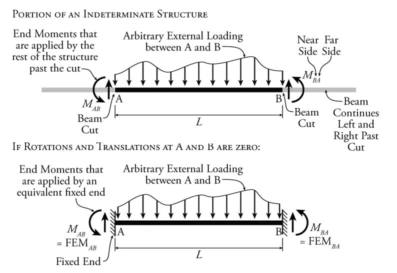



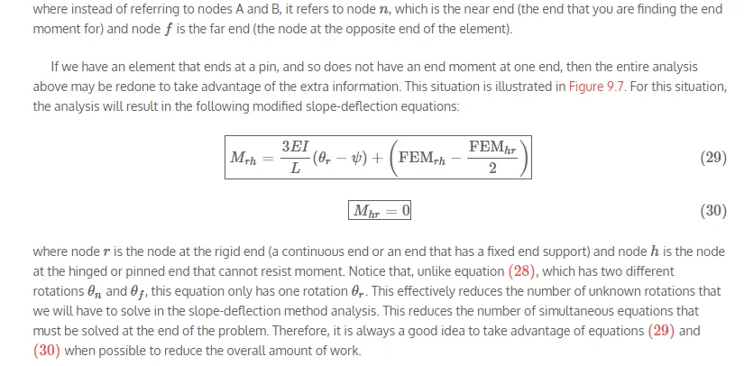

Figure 9.7: Free Body Diagram for a Finite Portion of an Indeterminate Structure with one End that Cannot Resist Moment

Comments are closed