
The slope-deflection method is an alternate way to analyse indeterminate structures. In many ways, it can be thought of as the opposite of the force method.
In the force method, we first identified redundant forces for the analysis and solved for them. In the slope-deflection method, we will first identify unrestrained degrees-of-freedom (DOFs, which are rotations or deflections) and solve for them. In the force-method, we found the redundant forces in terms of the deflections or rotations at the redundant force locations. In the slope-deflection method, we will find the deflections/rotations of the unrestrained DOFs in terms of the forces and moments at the DOF locations. In the force method, we solved for the unknown redundant forces by applying compatibility conditions at the redundant force locations. In the slope-deflection method, we will solve the deflections/rotations of the unrestrained DOFs by applying equilibrium conditions at the DOF locations. So, to in whenever we used a force or moment in the force method, we will use a deflection or rotation in the slope-deflection method, and vice versa.
The consequence of this is that, while the force method required us to solve a system of equations with as many equations/unknowns as there were redundants, for the slope-deflection method we will need to solve a system of equations with as many equations/unknowns as there are degrees-of-freedom (DOFs). So, where the force method was good at analysing indeterminate structures with a low number of degrees of indeterminacy, the slope-deflection method will be good for analysing highly-constrained structures, with a lot of degrees of indeterminacy, and not much freedom of movement (not many DOFs).
Degrees of Freedom
When doing structural analysis, we generally conceptualize a real structure as a simplified stick model with elements connected to each other at specific locations called nodes. Although the elements have deformations between the nodes, we can, using structural analysis methods, characterize the behaviour and deformation of the structure based on the deformations at the nodes alone.
A degree-of-freedom (or DOF) is a single way that a node is permitted to move or rotate. This concept was previously briefly introduced in Section 1.5. In a 2D system, each node has three possible degrees-of-freedom: translation (movement) in one direction, translation in another direction perpendicular to the first one, and rotation. Usually, we consider the horizontal and vertical axes as the two perpendicular translational degrees-of-freedom. Although three DOFs are possible for each node, individual directions may be considered to be restrained, either by a support reaction or by one of the connected members.
In slope-deflection method analysis, we will typically make the assumption that all frame members are axially rigid for the purposed of determining the number of degrees of freedom in the system (i.e. the beams cannot elongate or compress). This is usually a good assumption for beam and frame analysis since the vast majority of the structural deformations are caused by bending of frame elements, not axial elongation. By making this assumption, we reduce the number of effective DOFs in the slope-deflection analysis and, thus, reduce the number of equations in the system of equations that we have to solve.
A simple example is shown at the top of Figure 9.1 (labelled ‘Non-Sway Frame’). In this frame structure, we can look at each node individually to evaluate the total number of degrees of freedom in our system:
Nodes A and B
cannot translate (displace) horizontally or vertically and cannot rotate because of the fixed end support at that location. (Total DOFs = 0)
Node C
cannot translate (displace) either horizontally or vertically because of the pin at that location. It can rotate, and will have a rotation of θCθC as shown in the figure. (Total DOFs = 1)
Node D
cannot translate horizontally due to the restraint provided by member CD which is restrained horizontally by the pin at point C (recall that we are considering the frame members to be rigid axially). Node D cannot translate vertically due to the restraint provided by member AD which is restrained vertically by the fixed end at node A. It can rotate, and will have a rotation of θDθD as shown in the figure. The same rotation is applied to the ends of all three members that frame into node D (AD, CD, and DE). (Total DOFs = 1)
Node E
cannot translate horizontally due to the restraint provided by member DE which is restrained horizontally by member CD which is restrained horizontally by the pin at point C. Node E cannot translate vertically due to the restraint provided by member BE which is restrained vertically by the fixed end at node B. It can rotate, and will have a rotation of θEθE as shown in the figure. The same rotation is applied to the ends of both members that frame into node E (BE and DE). (Total DOFs = 1)
Adding up all of the DOFs for each node, we see that this structure has three total DOFs: θCθC, θDθD, and θEθE. So, for a slope-deflection method analysis, we would need to solve a system of three equations and three unknowns. Since one of the member ends has a pin support (at node C), we will be able to use a special formulation for the slope-deflection equations to reduce the number of equations to two (as we will see). This is an easy problem to solve by hand. If we used the force method to analyse this structure, we will have to solve a system of five equations and five unknowns since the structure is 5°5° indeterminate. This is all but impossible to do by hand.
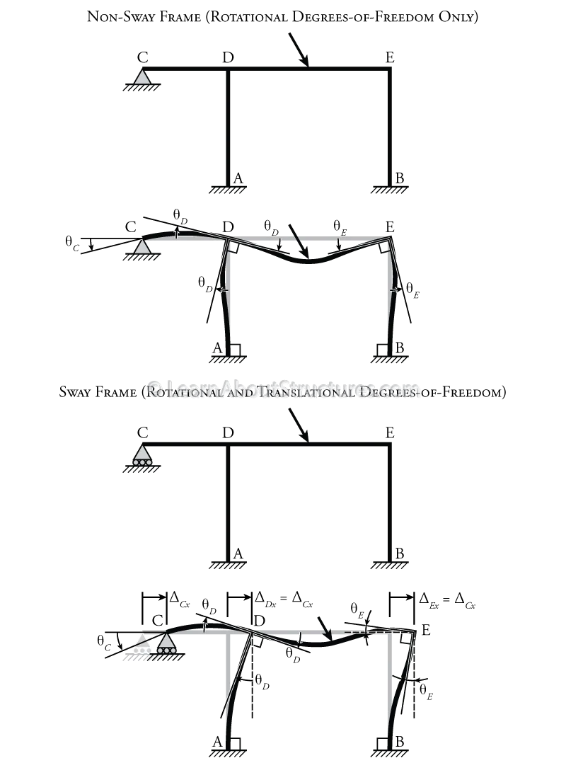
Figure 9.1: Degrees of Freedom
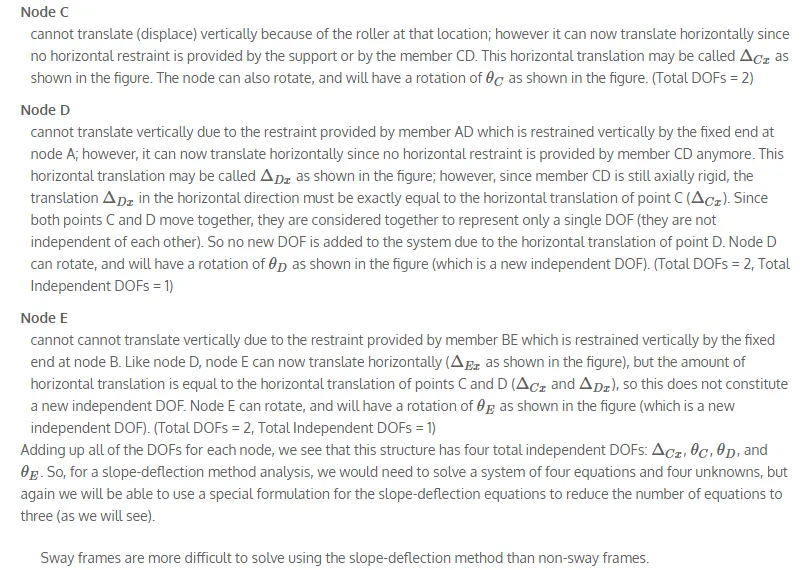
Since there are only rotational DOFs in this structure, and no translational DOFs (i.e. all nodes remain at the same points in space), then this top structure shown in Figure 9.1 is considered to be a non-sway frame. In contrast, a sway frame is a structure where any of the joints can translate or displace. The non-sway frame may be converted into a sway frame by removing the horizontal restraint at point C (converting the pin into a roller). The resulting structure is shown in the lower half of Figure 9.1.
We can again look at each node individually for the sway frame in Figure 9.1 to evaluate the total number of degrees of freedom in our system:
Nodes A and B
still cannot translate (displace) horizontally or vertically and cannot rotate because of the fixed end support at that location. (Total DOFs = 0)
