
Force Method for Support Settlements, Temperature Changes and Fabrication Errors
The force method may also be used to determine the effect of support settlement, temperature changes and fabrication errors on indeterminate structures. The latter two will only be discussed in terms of their effect on indeterminate structures, just as we previously discussed and analysed their effect on determinate structures
Support Settlements
Support settlements may be caused by soil erosion, dynamic soil effects during earthquakes, or by partial failure or settlement of supporting structural elements. Supports could also potentially heave due to frost effects (this could be considered a negative settlement)
For externally determinate structures, support settlements will simply cause a rigid body rotation of the structure. Although this movement may be undesirable, the settlement cannot cause any internal forces in the structure itself. This situation is shown at the top of Figure 8.23. On the other hand, for indeterminate structures, settlement of structural supports can induce internal shear and moments as shown in the middle of Figure 8.23. This is because an indeterminate structure is effectively over-constrained, i.e. there are more restraints than would be required for stability.

Figure 8.23: The Effect of Support Settlement on Indeterminate Beams
In Figure 8.23 an indeterminate beam is shown that has some support settlement at all three vertical support locations. It seems that the middle support at point C settles rather more than the others. So, this support effectively pulls down on the beam at point C, inducing bending in the beam. Now, of course, since all of the supports are settling to some extent in this example, the support at point C is not pulling down on the beam with a full effective displacement of ΔCΔC relative to the other two supports. It is only the portion of this settlement relative to the other two supports that causes bending in the beam.
We can think of this in terms of a determinate beam with supports at points A and E, where there is some action or load at point C that pulls the beam down at that location, causing bending in the beam. The determinate beam is not affected by the settlement of its supports at A and C, since support settlements do not cause moments in determinate beams as shown at the top of Figure 8.23. Instead, we would like to know how much point C moves down, relative to the determinate beam that can rotate freely as a rigid body. We can figure this out by drawing a straight line between points A and E (our determinate beam) and finding how far support C settles relative to that line.
This is a convenient way to think about things, especially when we are doing a force method analysis. In the force method, we already have a way to temporarily convert an indeterminate system into a determinate system for analysis by considering some of the forces as redundant. The determinate system that remains after we remove the restraints associated with the redundant forces is our primary system.
So, if we now consider the vertical reaction at point C (CyCy)to be our redundant force (as shown in Figure 8.23), then we can consider our remaining primary system (with supports at A and E) as the determinate system. We can then draw the chord of the primary system, which is just a straight line between points A and E (after they have settled). This chord represents the undeformed shape of the settled determinate primary system. Then, we can find how much the redundant support C has settled relative to the determinate system (
This is the amount of deformation at C which causes bending in the beam.
To consider this relative imposed displacement caused by the support settlement at point C using the force method, all we have to do is modify our compatibility condition. Previously, all of our compatibility conditions typically equated to zero, since the compatibility information that we are usually taking advantage of is that a support doesn’t move, or some member remains continuous. For example, for a typical force method analysis where a vertical reaction at C was used as the redundant force, then the compatibility condition may have looked something like:
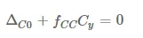
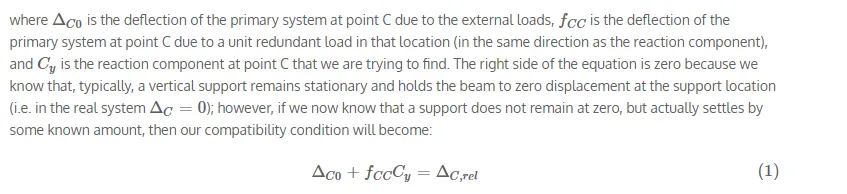
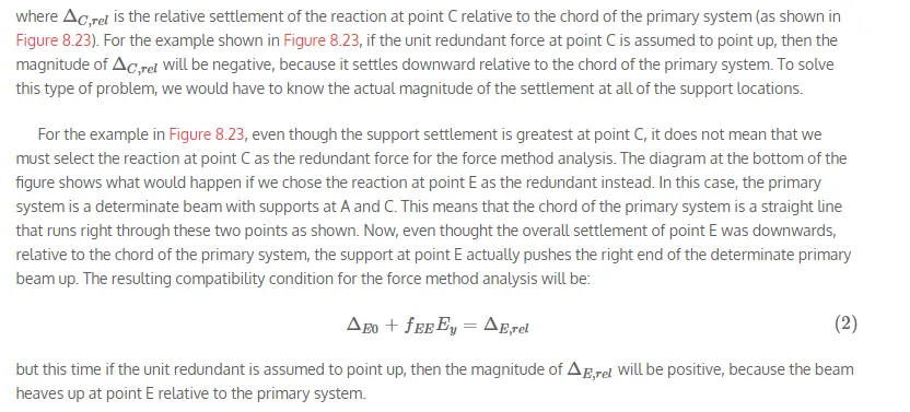
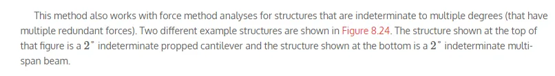
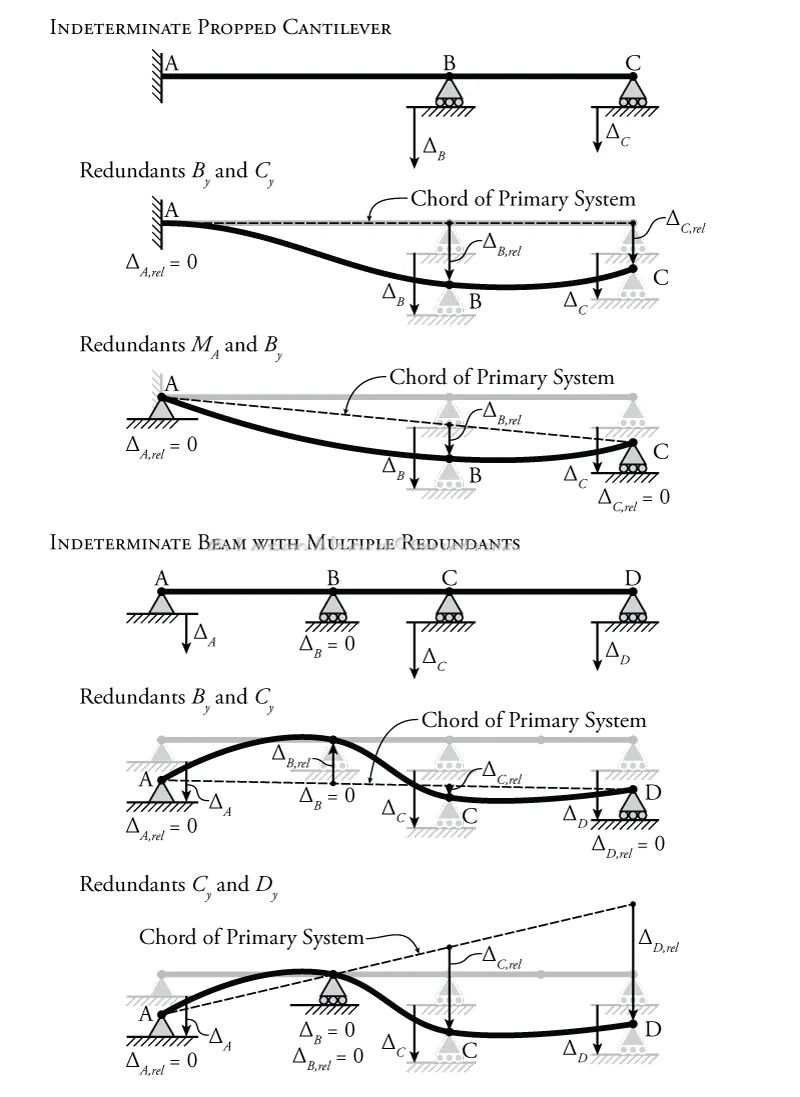
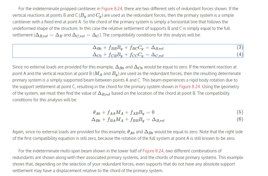
Figure 8.24: Selection of the Redundant Force in Force Method Analyses for Structures with Support Settlement

Comments are closed