
Steel beams are to be designed to suit the following limit states:
● Bending strength at ULS (including local buckling of flange or web, lateral torsional buckling, and plastic moment capacity)
● Lateral torsional buckling is checked when extreme fibres at the top part of the neutral axis of the steel beam is undergoing compressive stresses due to downward loads onto the beam. The applied loads creates compression in the top flange of the beam, where it buckles, and tension in the bottom flange of the beam. Torsional stresses will then be created due to the web resisting the flange from buckling along its length, but during this process, inducing twisting deflections.
● Shear strength at ULS
● The beam should be designed to resist shear forces parallel to the web of the beam.
● Web shear buckling
● Web shear buckling needs to be checked when the beam has a slender web. In this case, the shear capacity will then be governed by web shear buckling. Stiffeners can be erected on the web to resist web shear buckling. Moreover, if transverse forces are present and distributed from flanges into webs, web buckling would need to be further checked.
● Deflection at SLS
Sizing
The following are the typical minimum column section sizes for braced frames:
● 203 UC = up to 2-3 storeys high
● 254 UC = up to 5 storeys high
● 305 UC = up to 8 storeys high or long spans
● 354 UC = 8-12 storeys high
Scheme Design
1. Determine the live load on the beam
2. Find the allowable deflection based on unfactored imposed loads and check against maximum design deflections For beams, deflection is usually the most critical case for long spans and shear is usually the most critical case for beams with short spans and large loadings.
Allowable Deflection Limit = Live Load / 360
3. Find total ULS loads on the beam
Total load = Span x Load width x Critical Load x ULS factors
Steel structural members are designed to resist yielding, buckling, and rupture under ultimate forces. Beams are designed to resist ULS bending and shear forces.
4. Determine support conditions of the beam and determine effective lengths, L, based on the support conditions
5. Determine M, the maximum bending moment, and V, the maximum shear force
M = w x L
6. Determine the Second Moment of Inertia for the beam (where I has units of cm^4)
I = 0.5 x Ratio x K x L x M
where
M = maximum bending moment (kNm)
L = effective length of beam (m)
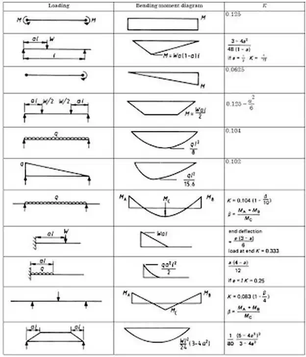
K = constant according to end supports and on bending moment diagrams. K values are also shown in the table below.

Comments are closed