Simple two-dimensional (2-D) truss structures are formed by combining one-dimensional linear members to create a triangular pattern. One starts with a triangular unit, and then adds a pair of members to form an additional triangular unit. This process is repeated until the complete structure is assembled. Figure 2.1 illustrates this process for the case where all the members are contained in a single plane. Such structures are called plane trusses; the nodes are also called “Joints.”
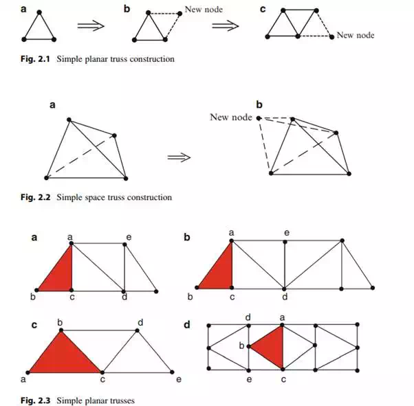
Three members connected at their ends form a rigid structure in the sense that, when loaded, the change in shape of the structure is due only to the deformation of the members. It follows that a structure constructed in the manner described above is also rigid provided that the structure is suitably supported.
Simple three-dimensional (3-D) space trusses are composed of tetrahedral units. Starting with a tetrahedral unit, one forms an additional tetrahedral unit by adding three linear elements, as illustrated in Fig. 2.2. When the structure is suitably supported to prevent rigid body motion, the assemblage is rigid. The question of suitable supports is addressed later in the chapter.
Examples of simple planar trusses are shown in Fig. 2.3. Starting with the initial triangle abc, one adds the nodes d, e, etc.
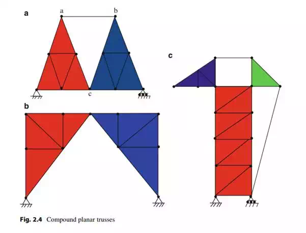
Trusses may also be constructed by using simple trusses as the “members,” connected together by additional bars or joints. These structures are called compound trusses. Figure 2.4 shows several examples of compound trusses, where the simple trusses are shown as shaded areas.
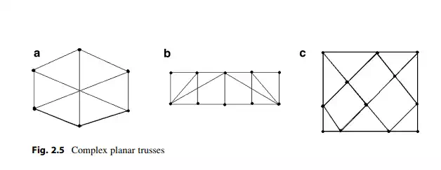
A truss geometry that does not fall in either the simple or compound category is called a complex truss. Examples are shown in Fig. 2.5. This type of truss is not used as frequently as either simple or compound trusses.
Structural Idealization
Trusses are components of larger structural systems, such as buildings, bridges, and towers. In order to evaluate the behavior under loading, one needs to identify the main structural components of the system and determine how the external load is transmitted from one component to another. This process is called “structural idealization,” it is a key step in the analysis process. In what follows, we illustrate idealization strategies for typical bridges and roof systems.
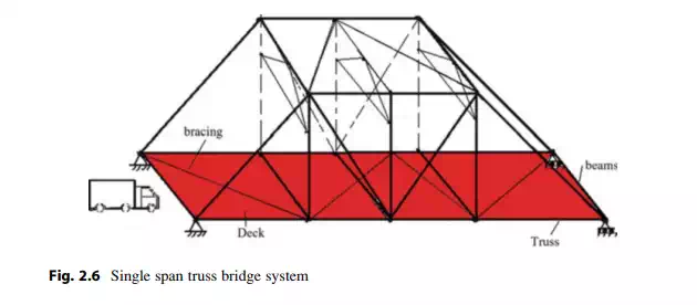
Figure 2.6 shows a typical single span truss bridge system. The key components are the two simple planar trusses, the lateral bracing systems at the top, sides, and bottom levels and the flooring system consisting of floor stringers/beams and deck slab. Loading applied to the deck slab is transmitted through the stringer/beam system to the bottom nodes of the two planar trusses. The major percentage of the analysis effort is concerned with analyzing a simple truss for dead weight, wind, and traffic loading.
Roofing system for buildings such as warehouses, shopping centers, and sports facilities employ trusses to support the roof envelope. Figure 2.7 illustrates a scheme for a typical roofing system for a single-story industrial building. The roof system consists of steel decking attached to purlins which, in turn, are supported at the top nodes of the planar trusses. Loading applied to the roof area in a bay is transmitted through the purlins to the trusses adjacent to the bay, and eventually to the supports. Bracing is incorporated to carry the lateral loading which may act either in the longitudinal or transverse direction. The primary effort for this structural system is concerned with analyzing a single planar roof truss for the tributary area loading applied at the top chord nodes.

Comments are closed