
The applied loads include direct compression forces, as well as, compressive and tensile stresses that are caused by sagging bending moments to the beam. The induced compressive stresses are located in the material fibres above the neutral axis of the member and the induced tensile stresses are located below the neutral axis.
1. Determine fy and fcu according to required material properties
2. Determine preliminary dimensions of the beam, b and h
3. Find effective depth, d
d = h – cover – bar diameter
Concrete covers are to be designed for requirements of fire resistance and durability.
4. Find span/depth ratio, L/d and make sure that L/d is less than 20
Deflection should be checked using the span/depth ratio.
Cracking should be designed for SLS and should meet the requirements of minimum reinforcement needed and spacing.
Detail Design
1. Find w
w = 1.4DL + 1.6LL
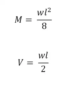
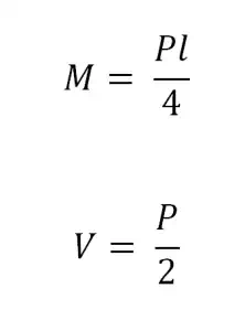
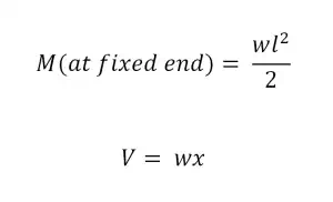
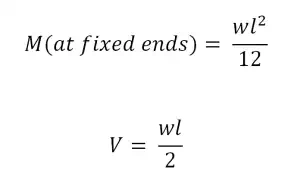
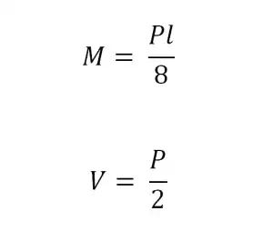
2. Find the design moment and shear, M and V
Simply supported with Uniformly Distributed Load
Simply supported with Concentrated Load
Cantilever Beam with Uniformly Distributed Load
Fixed ends with Uniformly Distributed Load
Fixed Ends with Concentrated Load at the Center
t
The effective span of beams, l, should be assumed to be the effective span of the member in its simply supported condition for conservative purposes. This span equals the exact distance between supports.
2. Establish concrete grade, fcu, in N/mm^2
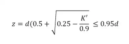
3. Find the depth to neutral axis, x, in mm
Depth to neutral axis, x, from compression face is limited to:
x ≤ 0.5d for fcu ≤ 45 N/mm^2
x ≤ 0.4d for 45 < fcu ≤ 70 N/mm^2
x ≤ 0.33d for 70 < fcu ≤ 100 N/mm^2
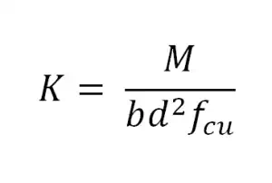
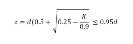
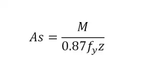
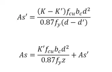
3. Design rectangular beams for flexure
The design ultimate moment M should be designed greater than the ultimate bending moment.
*Also applicable to flanged beams when the neutral axis of the beam lies within the flange
K’ = 0.156 for fcu ≤ 45 N/mm^2
K’ = 0.120 for 45 < fcu ≤ 70 N/mm^2
K’ = 0.094 for 70 < fcu ≤ 100 N/mm^2
If K ≤ K’, compression reinforcement not required
x = (d-z)/0.45 for fcu ≤ 45 N/mm^2
x = (d-z)/0.40 for 45 < fcu ≤ 70 N/mm^2
x = (d-z)/0.36 for 70 < fcu ≤ 100 N/mm^2
If K > K’, compression reinforcement required
x = (d-z)/0.45 for fcu ≤ 45 N/mm^2
x = (d-z)/0.40 for 45 < fcu ≤ 70 N/mm^2
x = (d-z)/0.36 for 70 < fcu ≤ 100 N/mm^2
The maximum amount of reinforcement in concrete members (beams, columns, or slabs) should not exceed 4%.
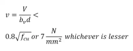
5. Design rectangular beams for shear
Shear stress in beams
Usually, the shear force and the shear stress should be obtained from the face of the support.
Shear reinforcement
Shear reinforcement should be designed for ULS and should be provided in the form of vertical links or bent-up bars. Shear forces are transferred to the vertical links that act with diagonal concrete struts in compression. Therefore, in beams, the links will act in tension and the concrete in compression.
Shear reinforcement are required to resist the following failure mode caused by shear:
● Inclined tensile cracks on beam
● Inclined tensile stress failure caused by shear
a. If v < 0.5vc, minimum links should be provided.
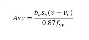
b. If 0.5vc < v < vc + vr, links should be provided, in which the area of shear reinforcement provided is
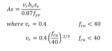
and where fcu not reater than 80.
c. If vc +vr < v < 0.8√fcu or v = 7 N/mm², links or links with bent-up bars should be provided. Links should not be more than 50% of shear resistance.
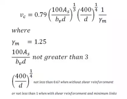
Concrete shear stress, vc
5. Determine whether maximum deflection is below deflection capacity
Allowable Limit = L/250


Comments are closed