
In the first scenario, the level of stress in a component reaches the ultimate stress for the material, causing a material failure, which, in turn, triggers a failure of the component. This type of failure depends on the stress–strain relationship for the material. Figure 1.6 illustrates the tensile stress–extensional strain response of tension specimens fabricated from two different types of materials [3, 4]. The behavior of the first material is essentially linear up to a peak stress, sf, at which point the material fractures and loses its ability to carry any load. This behavior is referred to as brittle behavior and obviously is not desirable from a structural behavior perspective.
The second response is completely different. The initial behavior is linear up to a certain stress value defined as the yield stress, ![]() For further straining, the stress remains essentially constant. Eventually, the material stiffens and ultimately fails at a level of strain which is considerably greater than the yield strain,
For further straining, the stress remains essentially constant. Eventually, the material stiffens and ultimately fails at a level of strain which is considerably greater than the yield strain, ![]() This behavior is typical for ductile materials such as the steels used in civil structures. In practice, the maximum allowable strain is limited to a multiple of the yield strain. This factor is called the ductility ratio (m) and is on the order of 5. Ductile behavior is obviously more desirable since a member fabricated out of a ductile material does not lose its load capacity when yielding occurs. However, it cannot carry additional loading after yielding since the resistance remains constant.
This behavior is typical for ductile materials such as the steels used in civil structures. In practice, the maximum allowable strain is limited to a multiple of the yield strain. This factor is called the ductility ratio (m) and is on the order of 5. Ductile behavior is obviously more desirable since a member fabricated out of a ductile material does not lose its load capacity when yielding occurs. However, it cannot carry additional loading after yielding since the resistance remains constant.
From a design perspective, the Structural Engineer must avoid brittle behavior since it can result in sudden catastrophic failure. Ductile behavior and the associated inelastic deformation are acceptable provided that the ductility demand is within the design limit. Limit state design is a paradigm for dimensioning structural components that assumes the component is at its limit deformation state and calculates the force capacity based on the yield stress.
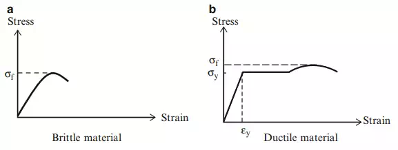
Fig. 1.6 Stress–strain behavior of brittle and ductile materials
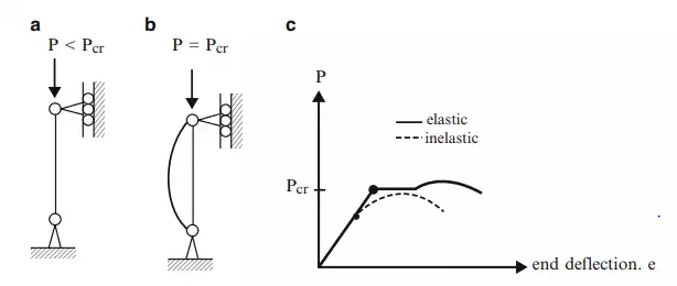
Fig. 1.7 Behavior of a flexible member
Buckling Failure Mode
Another possible failure scenario for a structural component is buckling. Buckling is a phenomenon associated with long slender members subjected to compressive loading. We illustrate this behavior using the member shown in Fig. 1.7a.
As the axial loading is increased, the member remains straight until a critical load value is reached. At this point, the member adopts a deflected configuration (Fig. 1.7b) with the load remaining constant. The member force remains essentially constant as the end deflection, e, is increased (Fig. 1.9c). This load deflection behavior is similar to inelastic action in the sense that the member experiences a large deflection with essentially no increase in load. For flexible members, the critical load for buckling (Pcr) is generally less than the axial compressive strength based on yielding, therefore buckling usually controls the design.
Priorities for Stability
Finally, summarizing and prioritizing the different concerns discussed in the previous sections, the highest priority is ensuring the structure is initially stable. If not stable, the structure will fail under an infinitesimal load. The second priority is avoiding buckling of the members. Buckling can result in large deformation and significant loss in load capacity for a member, which could cause the structure to lose its ability to support the applied loading. The third priority is limiting inelastic deformation of members under the extreme design loading. Although there is no loss in load capacity, the member cannot provide any additional load capacity, and therefore the deformation will increase significantly when the external loading is increased. We discuss this topic further in Sect. 1.4 where we present design philosophies.

Comments are closed