Design columns and other compression members where their vertical loads act concentrically to the neutral axis of the structural members. In these situations, these structural members are axially loaded by direct compressive stresses.
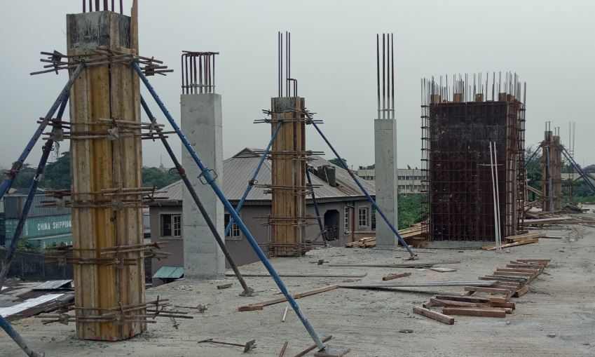
Concrete columns are structural members that help structural durability and resist and supports vertical loads. To distinguish concrete columns from concrete piers and walls, the bigger cross-section dimension should not be larger than four times its smaller dimension.
In practical applications, vertical loads act eccentrically to the neutral axis of the structural member. Therefore, in actual practice, both the compressive stresses that act concentrically to the neutral axis of the structural member AND the bending stresses induced by the compressive stresses that act eccentrically to the neutral axis of the structural member need to be accounted for in the structural design.
focus on compressive stresses that act concentrically to the neutral axis in scheme designs.
Concrete columns are considered to be braced when the overall structure is designed to resist lateral loads. Braced columns are columns in a stability system with shear or core walls. Unbraced columns are columns in a system where the only structural elements supporting the overall stability of the structure are the columns.
Columns are short if slenderness is less than 15 for braced columns or 10 for unbraced columns.
● Short columns – Crushing failure is caused by direct compression stresses
● Slender columns – Lateral buckling and crushing failure are caused by direct compression stresses and bending stresses caused by eccentric compression stresses. The amount of failure depends on the end fixity conditions and the slenderness ratio, which is effective length divided by radius of gyration.
1. Determine fy and fcu
2. Determine applied Live Load and Dead Load on the column
3. Determine tributary load area on the column
4. Determine the number of floors the column supports
5. Determine the total loads acting on the column by using the equation below
Total Load, N = (LL + DL) x ULS Factor x # of Floors x Tributary Load Area x Elastic Shear Factor
where LL = Live Load
DL = Dead Load
ULS Factor = 1.6 (for conservative purposes)
Elastic Shear Factor = 1.25
6. Determine the percentage of reinforcement the column should have and the X value. For example, if 3% reinforcement was chosen, we would use N/21.
Column area (Ac) can be estimated by
| Reinforcement Percentages for high yield steel | X in N/X |
| 1% | 15 |
| 2% | 18 |
| 3% | 21 |
The maximum amount of reinforcement in concrete members (beams, columns, or slabs) should not exceed 4%.
7. Determine the required concrete area
Ac_req = N/X
where X is value given in table above
8. Determine the dimensions of the concrete column that has dimensions, b and h, which would give Ac_prov = b x h > Ac_req
9, Determine applied moment on the columns
To estimate the applied moment on the columns, it is suggested to multiply the axial load from the floor above the column by:
● 25 – interior columns
● 5 – edge columns
● 2 – corner columns
Detail Design
1. Find the effective height, le, of the column
le = β x l
where l = full length
β = Values from table below
End condition 1 = column end is fully restrained by moment connection
End condition 2 = column end is partially restrained by monolithic connection
End condition 3= column end is simply supported
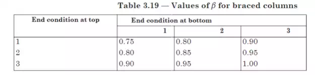
Source: (Clause 3.8.1.6, BS 8110)
2. Determine whether the column is a short column.
If ley / b < 15 and lex / h < 15, it is a short column.
If both ratios are larger than 15, it is a slender column.
where lex = effective height in respect of the major axis
ley = effective height in respect of the minor axis,
Normally, reinforced columns should be designed as short, not slender.
3. Find required area of steel reinforcement, Asc_req
Sufficient steel reinforcement content and reinforcement placement help to resist cracking in the concrete column. Additional reinforcement should be used, such as binders, vertical links, or ties. These additional reinforcement resist lateral buckling induced by compressive stresses of main reinforcement. A tie should be placed for every corner bar. The distance from one reinforcement bar to another should be no less than 150mm.
Reinforcement near the concrete surface are more effective at resisting bending moment forces than reinforcement placed at the centre of the column.
Equation for a short and braced column which supports roughly symmetrical arrangement of beams and where these beam properties and sizes do not differ by more than 15% is shown below.
N = 0.35 x fcu x Ac + 0.67 x Asc_req x fy
Where fcu = characteristic strength of concrete (N/mm^2)
Ac = area of concrete (mm^2)
Fy = yield strength of reinforcement (N/mm^2)
Asc = area of reinforcement
Note: If Asc_req is negative, use the equation below.
Asc_req = 0.4% x Ac_nominal
Note: The design moment for slender columns includes an additional moment induced by eccentricity of the geometry section.
4. Find a suitable number of reinforcement bars and the size of the reinforcement bars, ______ T ______
5. Find the area provided by the reinforcement bars designed, As_provided

Comments are closed