
We already discussed, that “spring equations” are “coupled”. You can’t simply say that a single “spring equation” describes the force/displacement relation between 2 nodes. Take a look at this drawing:
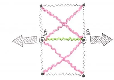
It’s obvious that when Node A and Node B “move apart” due to the load, the green spring will expand. Sadly, the red springs will expand as well. This is why the equations are “coupled”. It’s never just one spring reacting to any given deformation. It’s always a “set of springs”.
If that is the case, we should think what are we willing to “couple” in one set of equations? Doing “everything at once” would be pretty intensive when it comes to computing, so let’s limit ourselves to 4 nodes coupled together! In 2D that would be a “QUAD4” element – the most iconic FEA element I think! Thanks to this simplification we only have a few nodes and a couple of equations to worry about in one “set”. This will be easily solvable “mathematically speaking”.
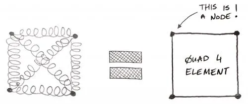
Basically, we just say: look those 4 Nodes are connected together with springs, and we will couple those “spring equations” together. This is what the “shape functions” really are – those “coupled spring equations” in one Finite Element! Of course, drawing all those springs in our CAE environment would be pretty problematic (and a bit inaccurate). So instead we will draw a quadrilateral shape that will show our 4 nodes in the corners – it’s a “nicer representation”, and it’s also a bit more accurate since springs are just a simplification. This way we can clearly see which 4 Nodes are connected together with our “shape functions” (or “coupled spring equations” if you prefer).
Interested in meshing?
As you can see, you don’t have to go through all the mathematics to understand how meshing works. You can learn with practical examples instead!
The last big “if”!
This sounds so nice and all, but of course, this is not the end of the story. There is one last thing we are missing: We have far more than a single Element, and they share Nodes!
Of course, each Element has “coupled spring equations”, and different Elements can share Nodes. This means that one single Node can have several “coupled equations sets” it’s involved with! Simply put, each Node can belong to more than one Element, and each Element will put its own shape functions onto the Node.
You know, something like this:
What is problematic here is, that Element A shape functions are “independent” from Element B shape functions. It’s a different set of coupled equations. This means that both those Elements will “interpret” what is going on in the common Nodes (2 and 5) differently!
What this means is, that firstly, solver gets the deformations at the nodes. Then knowing what is the deformation between nodes, using Element shape functions it can calculate strain in the Element. This is pretty simple – if Nodes 6 and 9 got closer to Nodes 5 and 8 this means that the Element D on the drawing above is compressed in the horizontal direction. Since we know how much closer those Nodes got together, and what was their relative position we know the “shortening” of the Element D… which gives us strain!
Knowing strain, we can easily calculate stress, knowing the stress-strain relation we implemented in our FEA model.
Should we vote on what the outcome is?
There is one final twist in this story! All Elements “agree” what the deformation on each Node is (this is a requirement for global stiffness matrix assembly of our model)! The problem is, this is the “only thing” they agree on!
Let’s take a look at our small FEA model once more:
If you would “ask” Element A what is the stress at node 5 it would say:
“Since Nodes 1, 2, 4, and 5 moved in relation to each other in *this way*, this means that the strain inside me looks like *that*. Based on that I predict that the stress in Node 5 is equal to Y”.
Ok, I admit, it’s a bit more complicated mathematically, since our Element only knows the correct strain/stress value in Gauss points located within its boundary, but let’s keep it simple ok? Let’s limit our today’s discussion to:
Since Element “knows” how its Nodes moved in relation to themselves it “knows” what the strain in this Element is. Thanks to that, it can calculate stress within this Element boundary.
Truth is, Element does not have the “full knowledge” of what is going on inside it. It only predicts couple of proper answers in so called Gauss Points, and just estimates/extrapolates those few correct answers on the “rest” of its area.
Now we can get to the point:
The above means that based on deformations of various Nodes “belonging” to each Element, all 4 Elements (A, B, C, and D above) will attempt to calculate stress value in the Node 5 in the middle.
The problem is, that each Element will obtain a different value, based on its own shape functions! You know, Element A will use relative movement between nodes 1, 2, 4, and 5 to calculate its strain while Element D will do the same thing, but for Nodes 5, 6, 8, and 9. Obviously, this will lead to different answers in Node 5!
This effectively means that in the central Node we get 4 different stress values! Which one is correct?
Well, all of them and none of them at the same time! Often your post-processing software will use something called “stress smoothing” or “stress averaging”. Instead of showing you this “jumping” stress contour plot (that in all honesty shows “real” outcomes from FEA), your post processor will simply calculate the average of all the values in the Nodes (from all Elements) and show you only the average. This looks more or less like this:
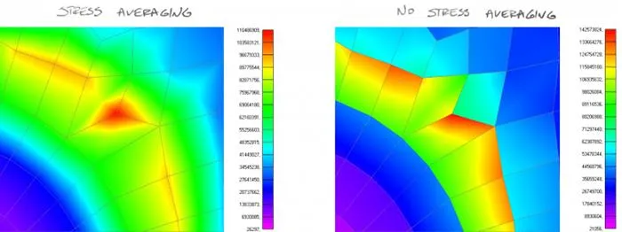
Basically what it means is, that you don’t see the “correct” answer in the Node of interest. But rather, an average from all the answers each Element sharing that Node is producing! When you decide to plot an “unaveraged” outcomes, instead of one stress value in any Node, you will obtain as many different nodal values as many Elements share this Node!
Cool huh!?
ok, I know it’s not cool at all! It bothered me as well. After all, a reasonable question is:
What is the outcome for crying out loud?!?
Mesh refinement for the rescue!
This is where Element size comes into play! Whatever model you have, on the sufficiently small scale the stress is almost constant in any given place. You just need to zoom close enough!
If you have a problem of big differences between nodal values in your model, the best approach then is to get the nodes closer to each other. Then, they are “almost in the same space”, so stress is “almost constant” and Elements will produce similar outcomes – a thing that we are interested in!
Also, Element quality is a factor. Shape functions work best if you have a square QUAD4 element. If this is not the case, and your Element has some sort of a “crazy shape” this is not helping! This will simply mean, that your Element may predict something “weird” simply because the shape of the Element makes the shape functions work improperly. This is why it’s always a good idea to take care to produce the mesh with good quality Elements (you can check Jacobians for that, or something from Barlows list in case of second-order 2D QUAD elements). I would say, however, that the Element size “helps more” than Element quality in typical situations (unless of course, you do something “weird” just to prove a point!).
Beyond the spring – warning this is a Geek section!
Above, I used a nifty explanation with the springs connecting Nodes in Finite Elements. To be completely honest, this is not how it works. I mean if you would mathematically “untangle” shape functions those would not lead to such a spring “system” in QUAD4 elements. In fact, it would be a bit more complicated.
You see, the Element does not calculate strain based on how much each spring in our simplified model elongated or shortened. That would be too simplistic. Instead, it solves some not too difficult equations.
