This page provides the sections on shear web beam bending from the “Stress Analysis Manual,” Air Force Flight Dynamics Laboratory, October 1986.
Other related chapters from the Air Force “Stress Analysis Manual” can be seen to the right.
Nomenclature
| Af | = | cross-sectional area of tension or compression flange | ||
| Cr | = | rivet factor | ||
| E | = | modulus of elasticity | ||
| Fs | = | allowable web shear stress | ||
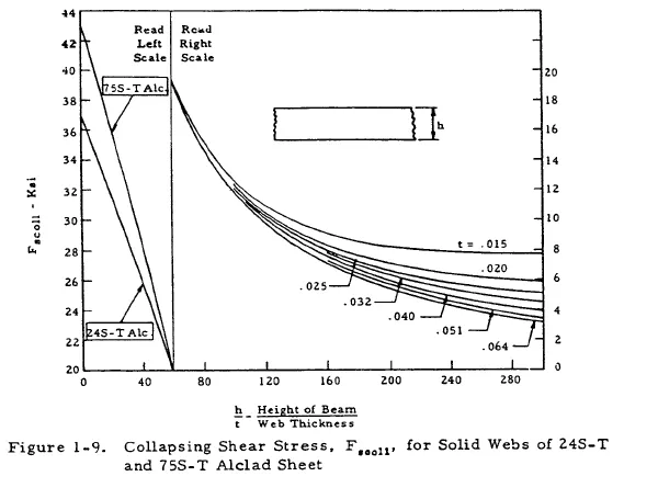
| Fscoll | = | collapsing shear stress for solid unstiffened webs | ||
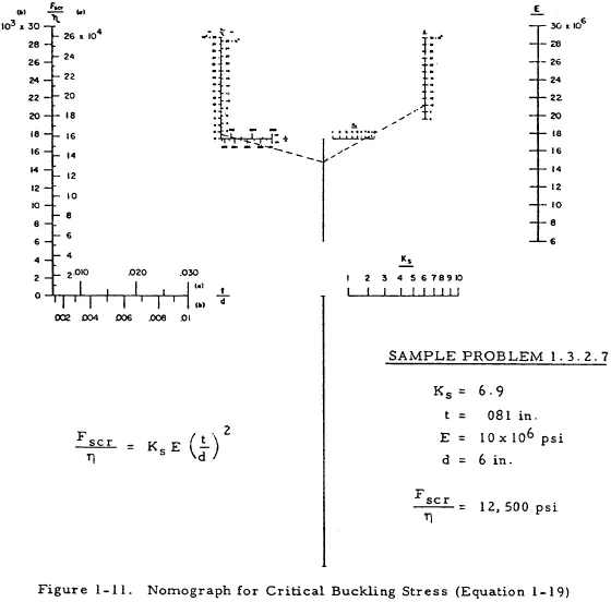
| Fscr | = | critical (or initial) buckling stress | ||
| fb | = | calculated primary bending stress | ||
| fs | = | calculated shear stress | ||
| h | = | height of shear web beam between centroids of flanges | ||
| I | = | moment of inertia | ||
| Iu | = | moment of inertia of upright or stiffener about its base | ||
| M | = | applied bending moment | ||
| p | = | rivet spacing | ||
| q | = | shear flow | ||
| t | = | thickness | ||
| V | = | shear force | ||
| η | = | plasticity coefficient | ||
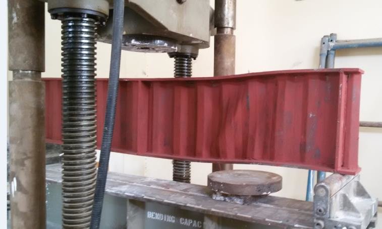
Introduction to Shear Web Beams in Bending
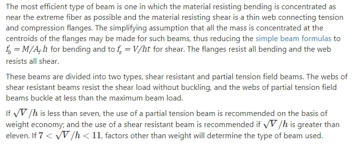
Introduction to Shear Resistant Beams in Bending
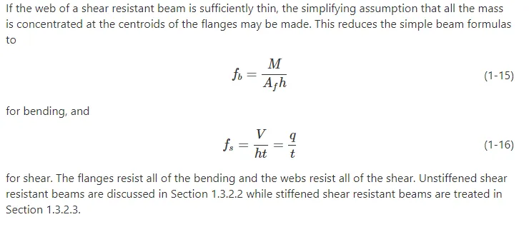
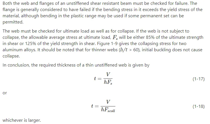
Unstiffened Shear Resistant Beams in Bending
Stiffened Shear Resistant Beams in Bending
The vertical stiffeners in a shear resistant beam resist no compressive load, as is the case for tension field beams, but only divide the web into smaller unsupported rectangles, thus increasing the web buckling stress. The flange web and rivets of such a beam must be analyzed.
Flanges of Stiffened Shear Resistant Beams
The flanges of a stiffened shear-resistant beam must be checked for yielding or ultimate strength by means of Equation (1-15) as in the case of unstiffened shear resistant beams.
Webs of Stiffened Shear Resistant Beams
The web panel of a stiffened shear-resistant beam must be checked for strength as well as for stability.
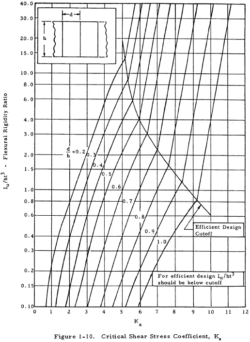
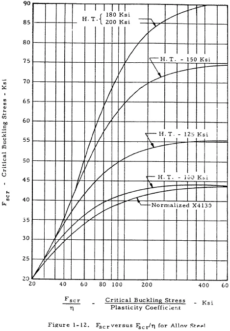
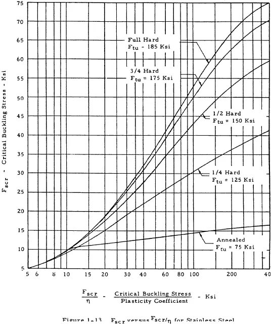
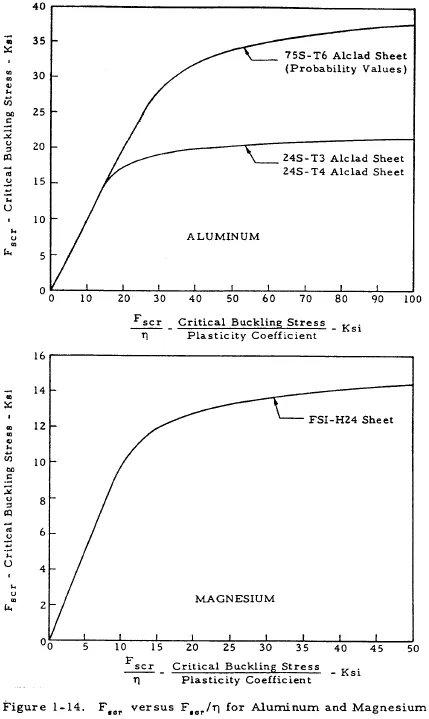
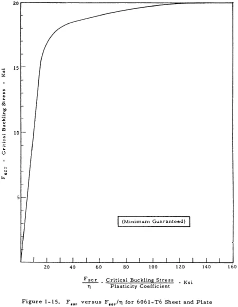
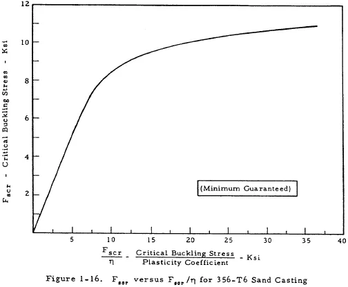
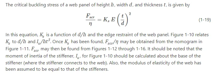
The strength of such a web may be checked by Equation (1-16) as in the case of unstiffened shear resistant beams, and the stability of such a beam may be checked by Equation (1-19) in conjunction with Figures 1-10 through 1-16.
Rivets in Shear Resistant Beams
Rivets are required to fasten the web to flange in shear resistant beams. In addition, rivets are used to fasten the web to the stiffener and the stiffeners to the flange in stiffened shear resistant beams.
Web-to-Flange Rivets in Shear Resistant Beams
The spacing and size of web-to-flange rivets should be such that the rivet allowable (bearing or shear) divided by q×p (the applied web shear flow times the rivet spacing) gives the proper margin of safety. The rivet factor, Cr (rivet spacing – rivet diameter/rivet spacing), should not be less than 0.6 for good design and in order to avoid undue stress concentration.
Web-to-Stiffener Rivets in Shear Resistant Beams
No exact information is available on the strength required of the attachment of stiffeners to web in shear resistant beams. The data in Table 1-4 is recommended.
| Table 1-4: Recommended Data for Web-to-Stiffener Rivets in Shear Resistant Beams | ||
| Web Thickness, in. | Rivet Size | Rivet Spacing, in. |
| 0.025 | AD 3 | 1.00 |
| 0.032 | AD 4 | 1.25 |
| 0.040 | AD 4 | 1.10 |
| 0.051 | AD 4 | 1.00 |
| 0.064 | AD 4 | 0.90 |
| 0.072 | AD 5 | 1.10 |
| 0.081 | AD 5 | 1.00 |
| 0.091 | AD 5 | 0.90 |
| 0.102 | DD 6 | 1.10 |
| 0.125 | DD 6 | 1.00 |
| 0.156 | DD 6 | 0.90 |
| 0.188 | DD 8 | 1.00 |
Stiffener-to-Flange Rivets in Shear Resistant Beams
No information is available on the strength required of the attachment of the stiffeners to flange. It is recommended that one rivet the next size larger than that used in the attachment of stiffeners to web or two rivets the same size be used whenever possible.
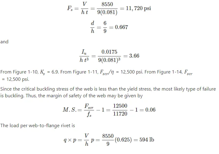
Sample Problem – Stiffened Shear Resistant Beams
Given: The beam shown in Figure 1-17 made of 75S-T6 Alclad.
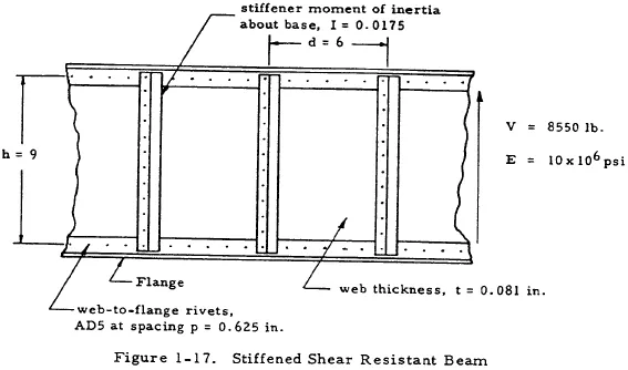
Find: The margin of safety of the web and the load on each web to flange rivet.
Solution: From Equation (1-16) the web shear stress is given by